Microsurgical balloon with protective reinforcement

a protective reinforcement and balloon technology, applied in the field of microsurgical balloons, can solve the problems of balloon damage, balloon damage, damage, etc., and achieve the effects of increasing the and increasing the longitudinal stiffness of the balloon

Active Publication Date: 2007-09-18
BOSTON SCI SCIMED INC
View PDF58 Cites 95 Cited by
  • Summary
  • Abstract
  • Description
  • Claims
  • Application Information

AI Technical Summary

Benefits of technology

[0009]In detail, the balloon is an elongated, inflatable balloon that defines a longitudinal axis. When fully inflated, the surface of the balloon is distanced radially from the longitudinal axis. For the present invention, at least one incising component is mounted on the outer surface of the balloon. Juxtaposed with, and parallel to, the incising component is a protective pad. The protective pad may be manufactured from a substantially impenetrable material or from a semi-penetrable material. Importantly, the protective pad may have an extended length, greater than the length of the incising component, to provide additional stiffness to the balloon in the longitudinal direction. The protective pad is positioned to engage the outer cutting surface of the incising component when the balloon is folded prior to insertion into the patient, or when the balloon is deflated after use in the vasculature. In an alternate embodiment of the present invention, a protective pad may also be positioned at one or both ends of the incising component, to engage the incising component in those instances when the balloon “kinks” or folds back along itself in a longitudinal direction.
[0011]With regard to the incising component, it is within the contemplation of the present invention that a plurality of incising components may be mounted axially, parallel to the longitudinal axis of the balloon. Further, a plurality of incising components may be axially aligned but azimuthally separated on the balloon. In yet another embodiment of the present invention, the incising component comprises an elongated blade and a base, with the base mounted on the outer surface of the balloon, and the blade mounted on the base. When the balloon is folded or deflated, the protective pad may engage either the base or the blade, thereby preventing the elongated blade from coming into contact with the balloon outer surface. The base may be shaped to increase the stiffness of the balloon in the longitudinal direction, thereby minimizing the possibility that the balloon will “kink” or fold back along itself. In addition, the base may be manufactured with one or more longitudinal stiffeners molded into the base. It is further contemplated by the present invention that the incising component may include an elongated tab at the proximal and distal end of the blade to increase the longitudinal stiffness of the balloon. The tab is an axial extension of the blade, and it is bonded to the outer surface of the base.
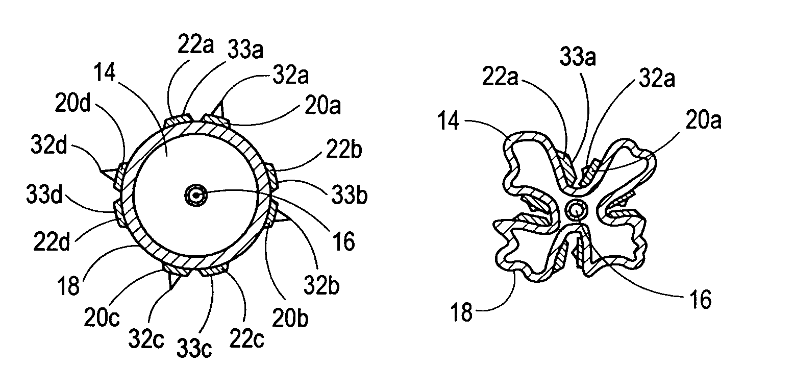
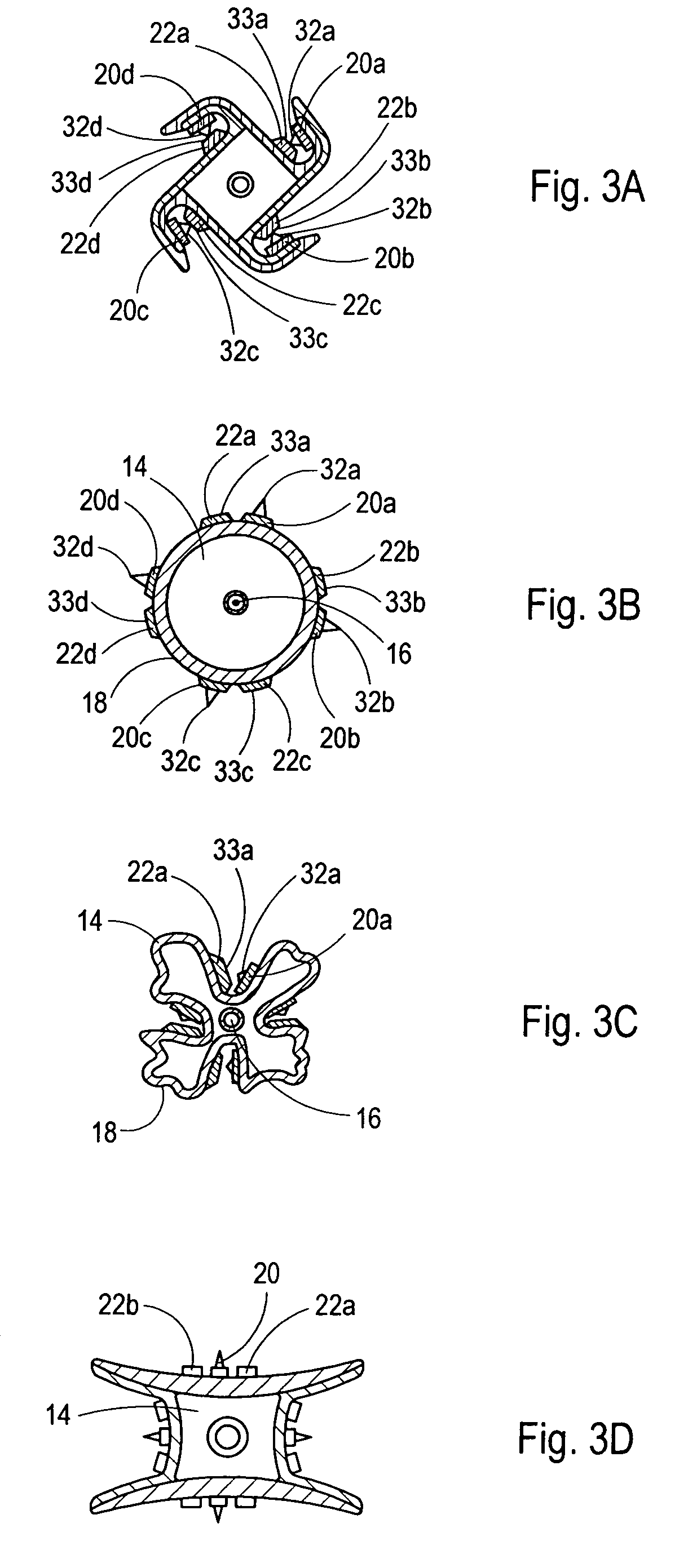
[0012]Prior to use, the inflatable balloon may be delivered by the manufacturer in a deflated, “folded” configuration. When folded, balloon material is wrapped circumferentially around the axis defined by the balloon. As contemplated by the present invention, when the balloon is folded, the protective pad engages the cutting surface of the incising component. This engagement effectively prevents the cutting surface of the incising component from coming into contact with, and damaging, the outer surface of the balloon.
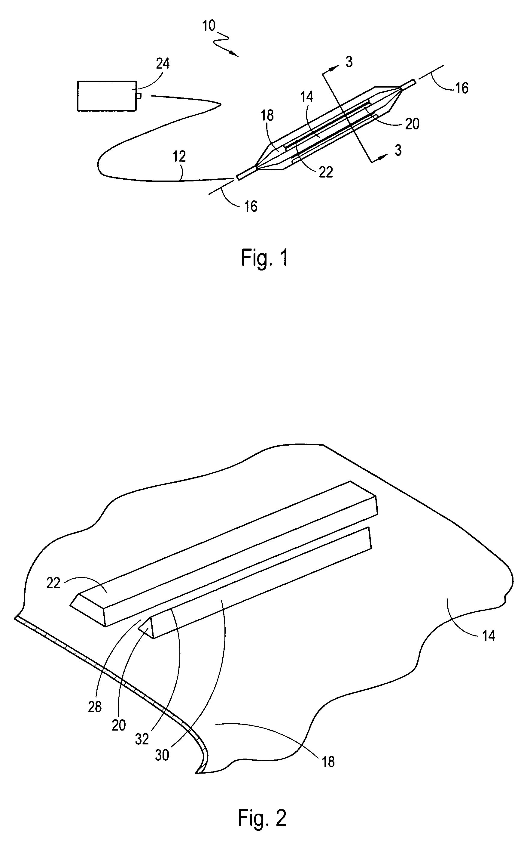
[0013]In operation, the folded balloon is inserted and advanced into the vasculature of a patient to perform a vessel dilation procedure. The increased longitudinal stiffness of the balloon helps to prevent “kinking” during insertion and removal, as the balloon strikes the vasculature wall or other obstructions. Once the balloon is properly positioned, a fluid source is used to inflate the balloon. This inflation then forces the incising component into the vessel wall of the patient to assist in the dilation of the vessel. After the dilation has been completed, the balloon is then deflated for removal from the vasculature system. When deflated, the balloon will collapse inwardly toward its longitudinal axis, returning the balloon to a modified “folded” configuration. As the balloon deflates, the protective pad again engages the cutting surface of the incising component to prevent an unwanted and inadvertent rupture of the balloon surface by the incising component. In this configuration, the incising component is also prevented from damaging the vessel wall of the patient.

Problems solved by technology

Regardless of the specific incising component that may be mounted on the balloon, a recurring problem is damage that may happen to the balloon during insertion of the catheter or after the balloon inflation and deflation sequence.
An incising component mounted on the surface of the balloon may, however, prevent the balloon from being folded into its most compact configuration, and may damage the balloon.
In addition, damage may occur as the balloon is being maneuvered through the vasculature of a patient.
Despite careful manipulation of the catheter through the vasculature system, balloon material may be pushed against the incising surface, damaging the balloon and causing an unwanted rupture.
Yet another opportunity for damage occurs after the balloon has been used for its intended purpose, and is subsequently deflated and withdrawn from the vessel.
When blades or other incising components are mounted on the balloon, to be located between the legs of the “X”, the balloon is particularly vulnerable to damage.
Specifically, damage can occur in this configuration if the balloon material is pushed against the incising component during passage through tortuous anatomy or during a twisting of the catheter.
In addition to the problems discussed above, balloon material may have a tendency to fold back on itself, along the axis of the balloon, as the distal end of the balloon contacts the vessel wall or obstructions in the vessel.
As such, the balloon will tend to fold back, or “kink”, in less rigid areas, potentially causing balloon material to fold over and come into contact with the incising component.

Method used


Image

  • Microsurgical balloon with protective reinforcement
  • Microsurgical balloon with protective reinforcement
  • Microsurgical balloon with protective reinforcement

Examples


Embodiment Construction

[0028]A system in accordance with the present invention is shown in FIG. 1 and is generally designated 10. As shown, the system 10 has a catheter 12, and an inflatable microsurgical balloon 14 that is attached to the catheter 12. The balloon 14 is an elongated, inflatable balloon 14 that defines a longitudinal axis 16. Mounted on the outer surface 18 of the balloon 14 is an incising component 20. As shown in FIG. 1, positioned substantially parallel to and juxtaposed with the incising component 20 is a protective pad 22. In the preferred embodiment of the present invention, the incising component 20 and the protective pad 22 are mounted on the outer surface 18 of the balloon 14 in a manner well known in the pertinent art, such as by adhesive bonding. The protective pad 22 may be manufactured from a substantially impenetrable or a semi-penetrable material. As further shown in FIG. 1, the system 10 includes an extracorporeal fluid pump 24 that is connected to the catheter 12. The extr...


PUM


Abstract

A microsurgical balloon, with at least one incising component mounted to the surface of the balloon, includes a protective pad to prevent the outer surface of the incising component from coming into contact with and damaging the balloon surface. In particular, the protective pad is positioned on the outer surface of the balloon substantially parallel to and juxtaposed with the incising component. When the balloon is in a deflated configuration, either for insertion into the vasculature system or removal from the patient, the protective pad engages the outer surface of the incising component thereby protecting the balloon from being punctured or damaged by the incising component. The protective pad may be bonded to the outer surface of the balloon, or it may be an integral part of a homogeneous balloon structure.

Description

FIELD OF THE INVENTION[0001]The present invention pertains generally to interventional medical devices. More particularly, the present invention pertains to microsurgical balloons that are used to insert incising components into the vasculature system of a patient. The present invention is particularly, but not exclusively, useful as a device and method for protecting the surface of the microsurgical balloon from damage or puncture caused by the balloon outer surface coming into contact with the incising component.BACKGROUND OF THE INVENTION[0002]Angioplasty is a well known technique that is commonly used in the treatment of vasculature diseases. An integral part of an angioplasty procedure is the insertion of an inflatable balloon on a catheter into the vasculature of a patient to position the balloon in a vessel at the site of a stenosis. The balloon is then inflated to dilate the stenosis.[0003]A recent innovation in angioplasty procedures involves ablation of a stenosis by an in...

Claims


Application Information

Patent Timeline
Patent Type & Authority Patents(United States)
IPC IPC(8): A61B17/22A61B17/00A61F2/958
CPCA61B17/320725A61B17/320758A61M25/1002A61B2017/00539A61B2017/00778A61B2017/22051A61B2017/22061A61M2025/1004A61M2025/1086
Inventor YEE, CARLROMAN, RICARDOSCHWAB, BRANDON
Owner BOSTON SCI SCIMED INC
Why Eureka
Try Eureka