Eureka AIR delivers breakthrough ideas for toughest innovation challenges, trusted by R&D personnel around the world.

Arrangement of color pixels for full color imaging devices with simplified addressing

a technology of color pixels and full color imaging, applied in semiconductor devices, identification means, instruments, etc., can solve problems such as non-optimal stripes of single colors, and achieve the effect of improving perceived resolution and appearan

Inactive Publication Date: 2007-09-25
SAMSUNG ELECTRONICS CO LTD
View PDF161 Cites 39 Cited by
  • Summary
  • Abstract
  • Description
  • Claims
  • Application Information

AI Technical Summary

Benefits of technology

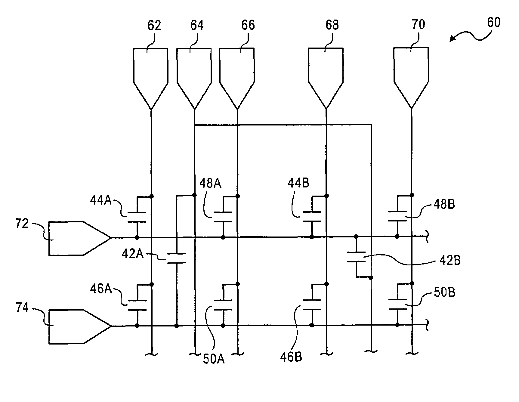
The invention is about a display with three-color pixels arranged in rows and columns. This arrangement matches the human vision system, providing better resolution and appearance of single full-color displays. The invention also includes a drive matrix for the pixel array, which reduces the number of drive lines and associated driver electronics used in the prior art. The technical effects of the invention are improved perceived resolution and appearance of full-color displays with reduced complexity of the drive matrix.

Problems solved by technology

The problem with the prior art is that in providing the same matched resolution balance between human vision and display, additional display panels / planes are used, along with additional driver electronics.
Since conventional stripes have limited the Modulation Transfer Function (MTF), high spatial frequency resolution, in the horizontal axis, stripes of a single color are non-optimal.

Method used


Image

  • Arrangement of color pixels for full color imaging devices with simplified addressing
  • Arrangement of color pixels for full color imaging devices with simplified addressing
  • Arrangement of color pixels for full color imaging devices with simplified addressing

Examples


Embodiment Construction

[0015]Those of ordinary skill in the art will realize that the following description of the present invention is illustrative only and not in any way limiting. Other embodiments of the invention will readily suggest themselves to such skilled persons.

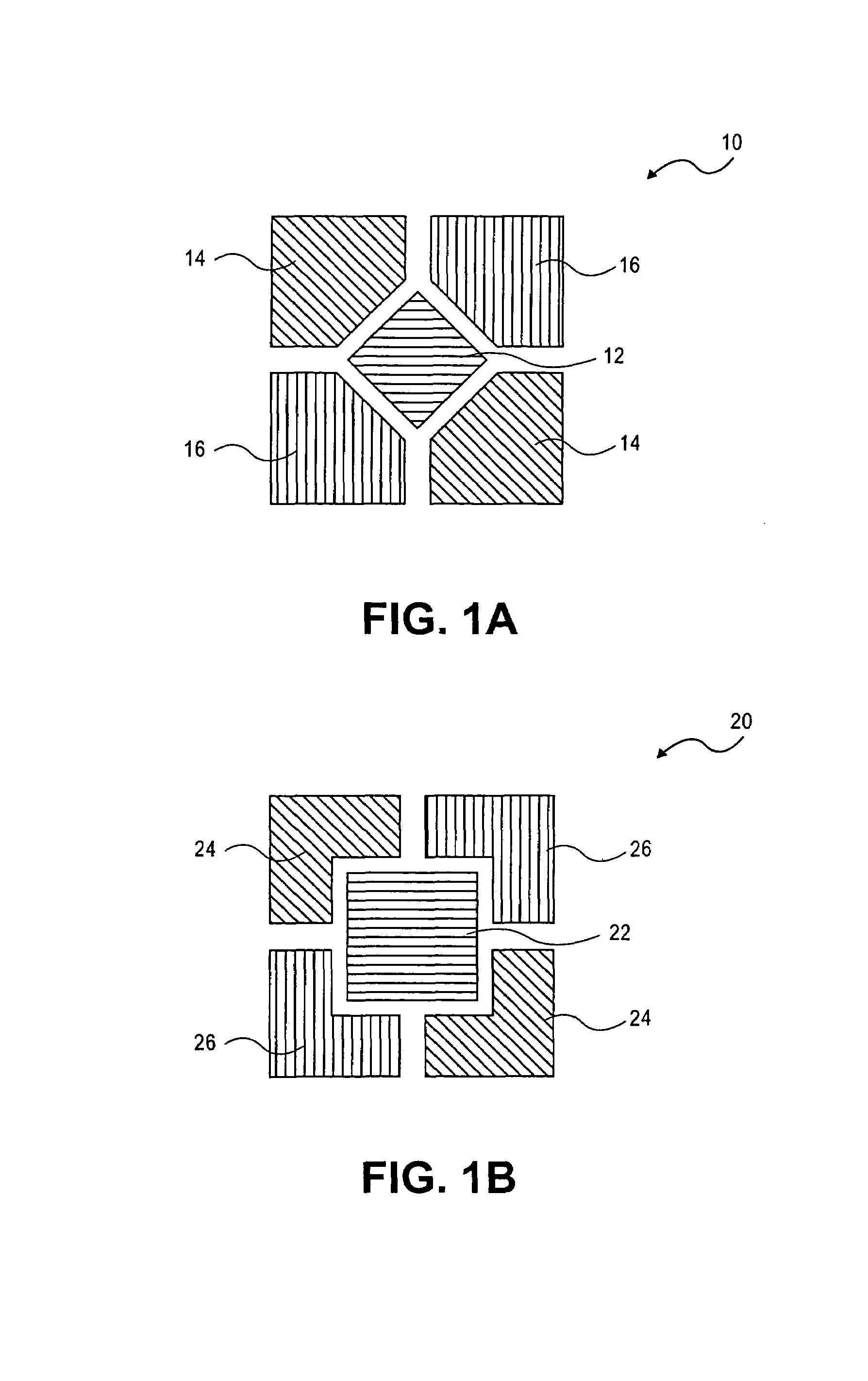
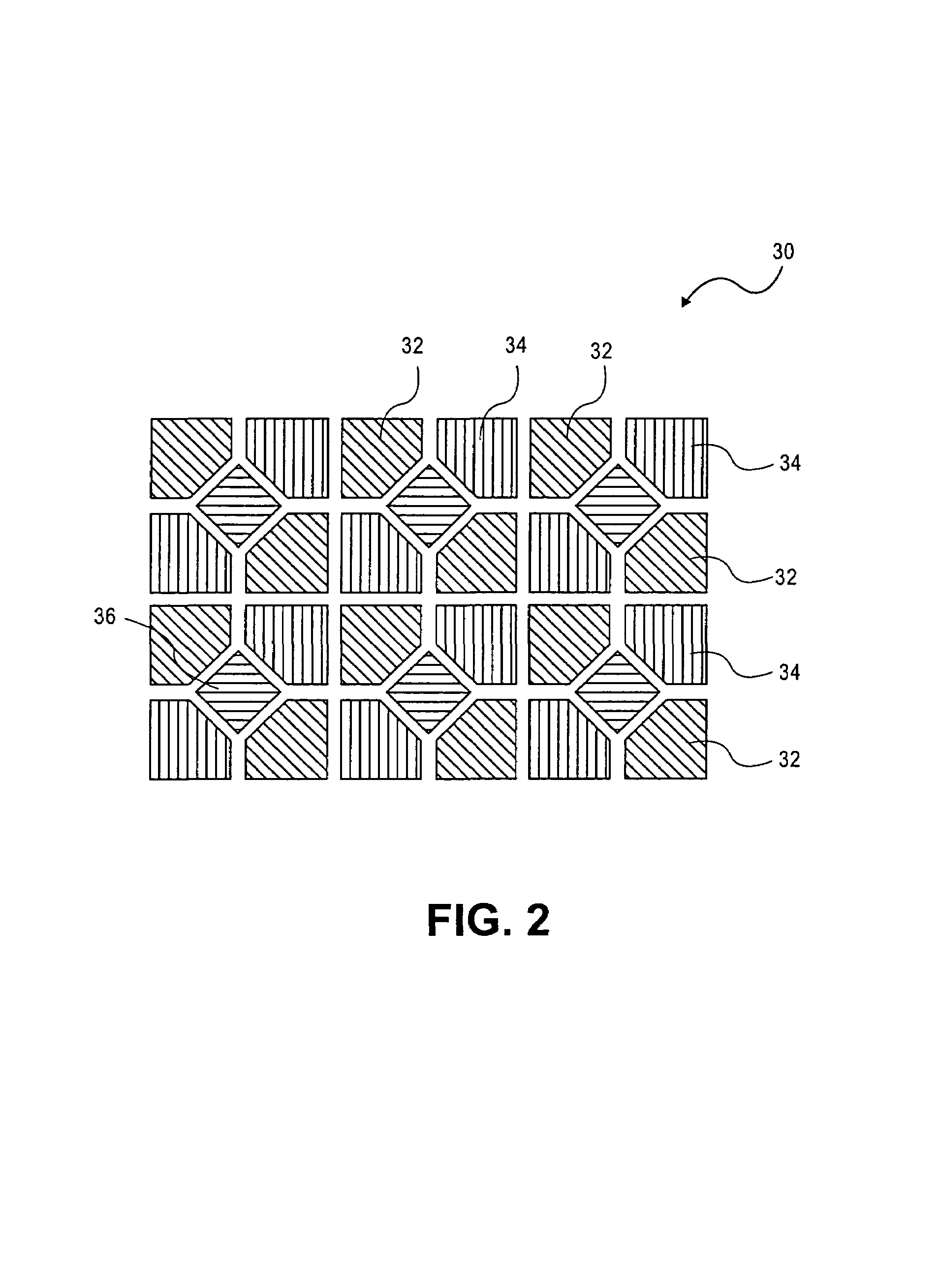
[0016]FIG. 1a shows an illustrative embodiment of an arrangement of a three-color pixel element 10 according to the present invention. The pixel element consists of a blue emitter 12, two red emitters 14, and two green emitters 16. The blue emitter 12 is disposed at the origin of a rectangular coordinate system having four quadrants, and the pair of red emitters 14, and the pair of green emitters 16 are disposed at opposing quadrants of the rectangular coordinate system. As shown in FIG. 1a, the blue emitter 12 is square shaped, having corners aligned at the x and y axes of the rectangular coordinate system, and the opposing pairs of red 14 and green 16 emitters are generally square shaped, having truncated inwardly-facing corners formi...


PUM

PropertyMeasurementUnit
viewing distanceaaaaaaaaaa
internal anglesaaaaaaaaaa

Abstract

A three-color pixel element for a display comprises a blue emitter disposed at the origin of a rectangular coordinate system having four quadrants, a pair of red emitters and a pair of green emitters spaced apart from the blue emitter and symmetrically disposed about the origin of the rectangular coordinate system in a first and second pair of opposing quadrants.

Description

BACKGROUND OF THE INVENTION[0001]1. Field of the Invention[0002]The present invention relates to color pixel arrangements. Specifically the present invention relates to color pixel arrangements used in electronic imaging devices and displays.[0003]2. The Prior Art[0004]Full color perception is produced in the eye by three-color receptor nerve cell types called cones. The three types are sensitive to different wave lengths of light: long, medium, and short (“red”, “green”, and “blue” respectively). The relative density of the three differs significantly from one another. There are slightly more red receptors than green. There are very few blue receptors compared to red or green. In addition to the color receptors there are relative wavelength insensitive receptors called rods that contribute to monochrome night vision.[0005]The human vision system processes the information detected by the eye in several perceptual channels; luminance, chromanance, and motion. Motion is only important...

Claims


Application Information

Patent Timeline
Patent Type & Authority Patents(United States)
IPC IPC(8): G09G5/02G09G3/28G09G3/32G09G3/36G02F1/1335G02F1/133G02F1/1343G09F9/30
CPCG09G3/3607G09G3/3614H01L27/3218G09G2320/0247H01L27/3216G09G2300/0452H10K59/352H10K59/353G02F1/13
Inventor BROWN ELLIOT, CANDICE HELLEN
Owner SAMSUNG ELECTRONICS CO LTD
Why Eureka
Eureka Blog
Learn More