Wind turbine dump load system and method

a wind turbine and dump load technology, applied in the direction of electric generator control, machine/engine, dynamo-electric converter control, etc., can solve the problems of large and rapid forces, and achieve the effect of avoiding excessive unloading of the generator and avoiding a heavy acceleration of the rotor

Active Publication Date: 2007-10-02
GE INFRASTRUCTURE TECH INT LLC
View PDF19 Cites 40 Cited by
  • Summary
  • Abstract
  • Description
  • Claims
  • Application Information

AI Technical Summary

Benefits of technology

[0005]A dump load resistor is included in the power circuit of a wind turbine. When a grid loss occurs, the dump load resistor immediately applies an electrically adsorbing load to the generator and thereby avoids excessively unloading the generator and wind turbine. The dump load resistor applies a load to the generator for at least a few seconds until the speed of the rotor is reduced, e.g., by blade pitching. This procedure avoids a heavy acceleration of the rotor. Other energy storage devices, e.g., a fly wheel, can also be used.
[0006]The dump load resistor avoids the rapid increase in rotor speed leading to a severe braking procedure that again lead to large and rapid forces, e.g., a bending moment, applied to wind turbines when a grid loss occurs. The dump load resistor allows the wind turbine to be designed to withstand much smaller grid loss loads that is required of typical wind turbine designs.

Problems solved by technology

The dump load resistor avoids the rapid increase in rotor speed leading to a severe braking procedure that again lead to large and rapid forces, e.g., a bending moment, applied to wind turbines when a grid loss occurs.

Method used


Image

  • Wind turbine dump load system and method
  • Wind turbine dump load system and method
  • Wind turbine dump load system and method

Examples


Embodiment Construction

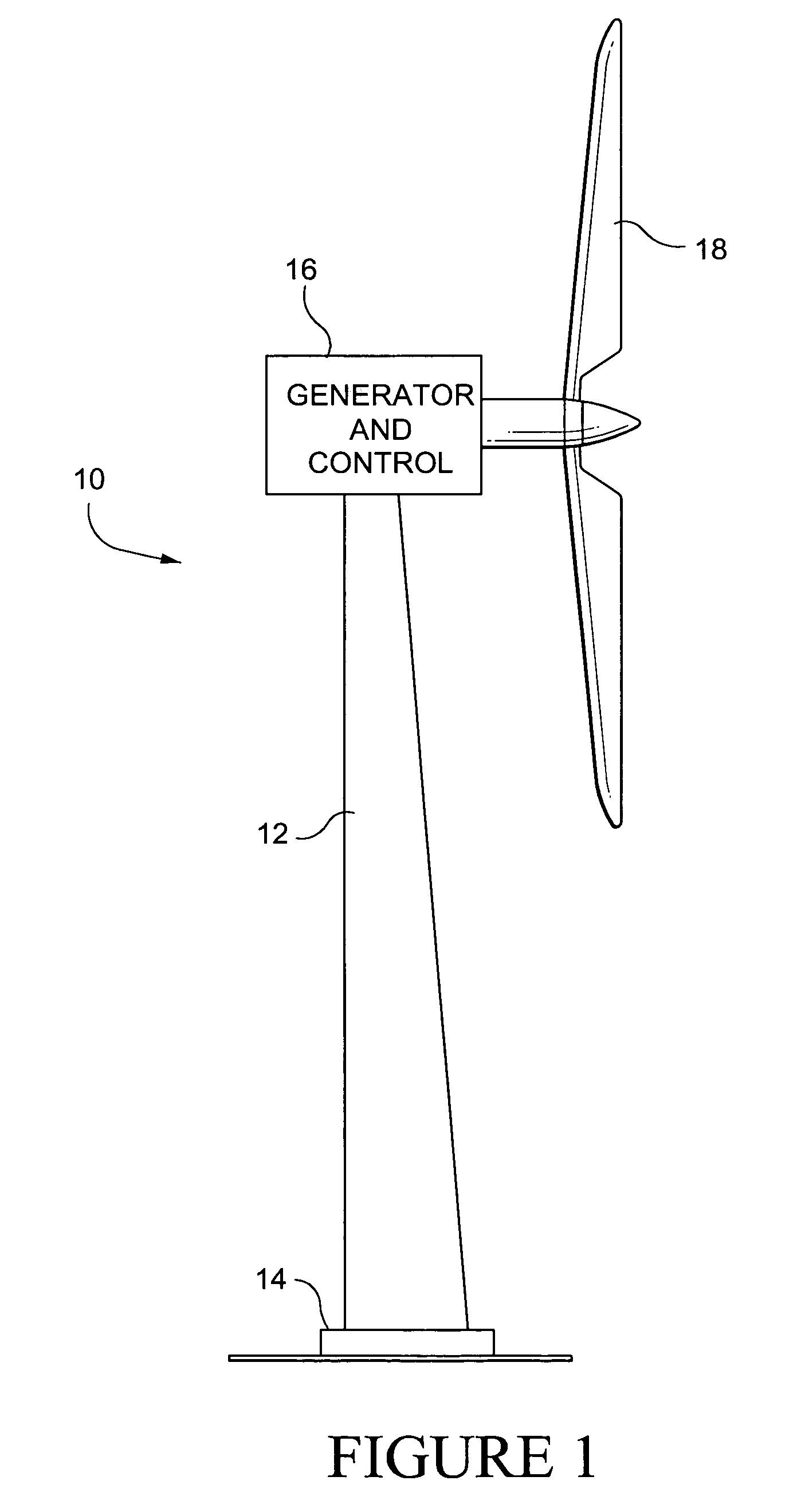
[0015]FIG. 1 is a schematic view of a wind turbine system 10. The wind turbine may include a tower 12 mounted on a base 14 and capped with a wind turbine 16 having a plurality of large blades 18. Wind turns the blades which drive the generator. The pitch of the blades of the wind turbine may be adjusted by a conventional gearing device.

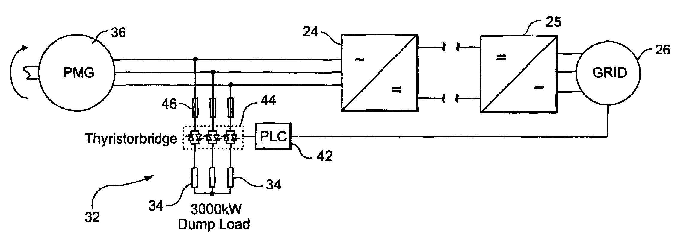
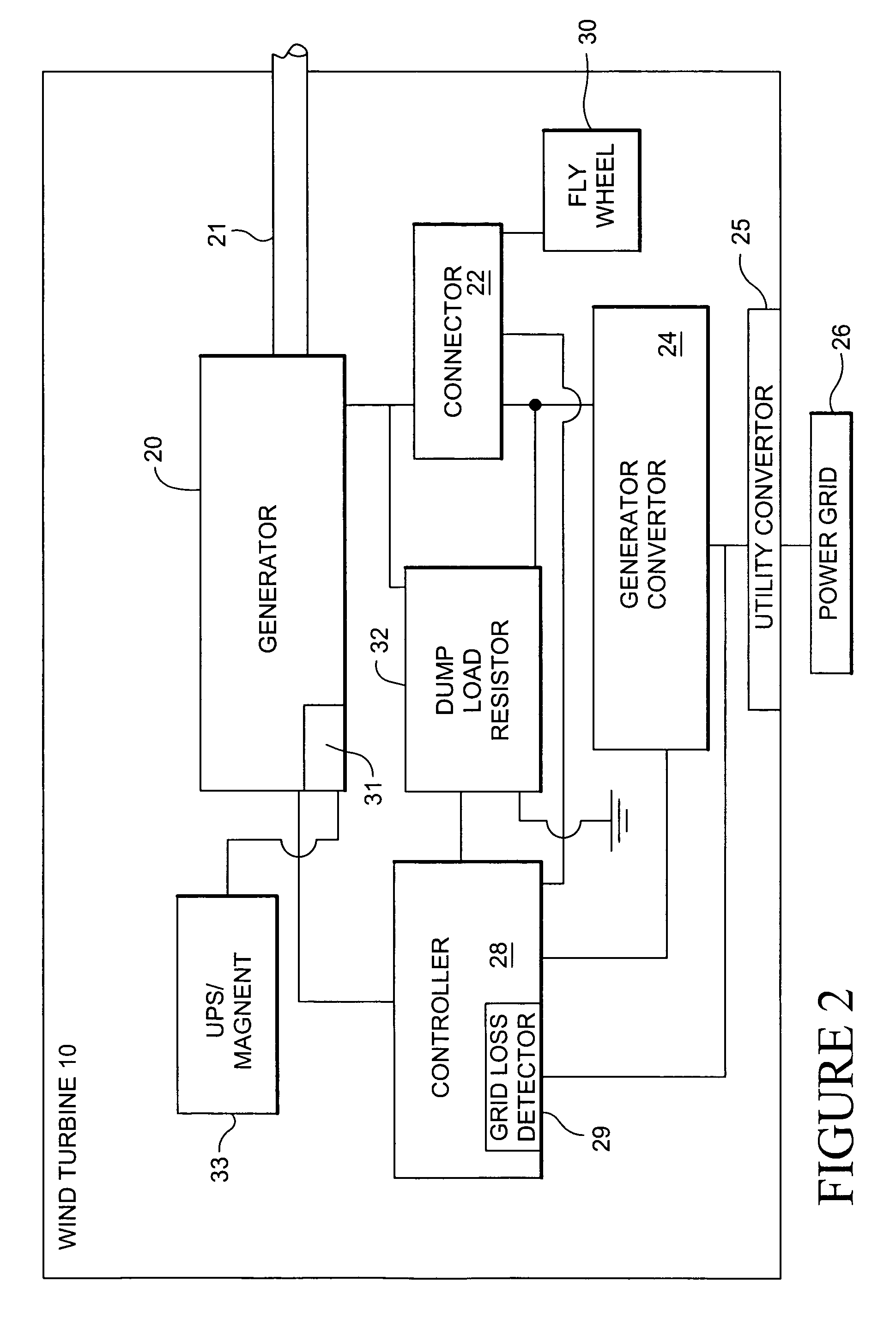
[0016]FIG. 2 is a high level block diagram of certain components of the wind turbine 10. The generator 20 includes a rotor that is rotationally driven by a shaft 21 turned by the blades of the wind turbine. Electrical power from the generator is transferred through a connector 22 to a generator converter 24. The generator converter 24 may be coupled to a utility grid power converter 25 that is in turn coupled to a power grid 26 is a conventional manner. The utility grid power converter may be mounted on the ground near the wind turbine base 14 and serve one or more wind turbines 10.

[0017]The exciter 31 for the rotor of the generator may be driven by a...


PUM


Abstract

A wind turbine braking system including: a wind turbine including turbine blades and a control system; a generator coupled to the turbine blades; a generator converter coupled to the generator and connectable to a utility power grid; at least one dump resistor coupled to the generator and generator converter, and if the utility power grid losses power, the dump resistor applying an electrical load to the generator converter.

Description

BACKGROUND OF THE INVENTION[0001]The invention relates to the generation and distribution of electric power generated by wind turbines. More particularly, the invention relates to adapting to rapid losses of electrical power loads on a wind turbine, such as the loss of an electrical power grid load.[0002]Power transmission and distribution grids (“power grids”) transmit electrical energy from wind turbine generating facilities to electrical power customers. The power grid provides an electrical load for a wind turbine generator. The electrical load on the generator imposes a torque on the rotor of the generator. The rotor is turned by the wind turbine which in turn is rotated by the wind. The torque on the rotor from the grid load results in a torque applied to the wind turbine. The wind turbine is balanced based on the torque from the grid load. If the grid load is loss the wind turbine may become unbalanced.[0003]Loss of the grid unloads the generator and typically results in a ra...

Claims


Application Information

Patent Timeline
Patent Type & Authority Patents(United States)
IPC IPC(8): H02P9/00
CPCH02H7/067F03D7/0288F03D7/0284F05B2270/1071Y02E10/723F05B2270/337F05B2260/903F05B2270/1011H02P3/22H02P9/10Y02E10/72
Inventor LUETZE, HENNINGEDENFELD, THOMASGAUCHEL, PETER
Owner GE INFRASTRUCTURE TECH INT LLC
Why Eureka
Try Eureka