Single-pole multi-throw switch having low parasitic reactance, and an antenna incorporating the same

a multi-throw switch and low parasitic reactance technology, applied in the field of single-pole multi-throw switches, can solve the problems of inability to achieve, several flaws, and the effect, in this embodiment, is likely to be undesirabl

Active Publication Date: 2007-10-02
HRL LAB
View PDF195 Cites 227 Cited by
  • Summary
  • Abstract
  • Description
  • Claims
  • Application Information

AI Technical Summary

Problems solved by technology

Furthermore, the numerous examples of microstrip switches available in the commercial marketplace do not directly apply to this invention because they typically use PIN diodes or FET switches, which carry certain requirements for the biasing circuit that dictate the geometry and which are not convenient for use in a radial design.
However, there may be situations in which this is not possible, or when one cannot achieve the required characteristics in a monolithic solution, such as a large fan-out number for example.
While the design depicted by FIG. 1 is believed to be novel, it has several flaws.
The effect, in this embodiment, is likely to be undesirable.
Unfortunately, the second pair of ports 3, 4 likely may not be brought any closer to the first pair 1, 2, because this would cause unwanted coupling between the closely spaced sections of microstrip line that would result.

Method used


Image

  • Single-pole multi-throw switch having low parasitic reactance, and an antenna incorporating the same
  • Single-pole multi-throw switch having low parasitic reactance, and an antenna incorporating the same
  • Single-pole multi-throw switch having low parasitic reactance, and an antenna incorporating the same

Examples


Embodiment Construction

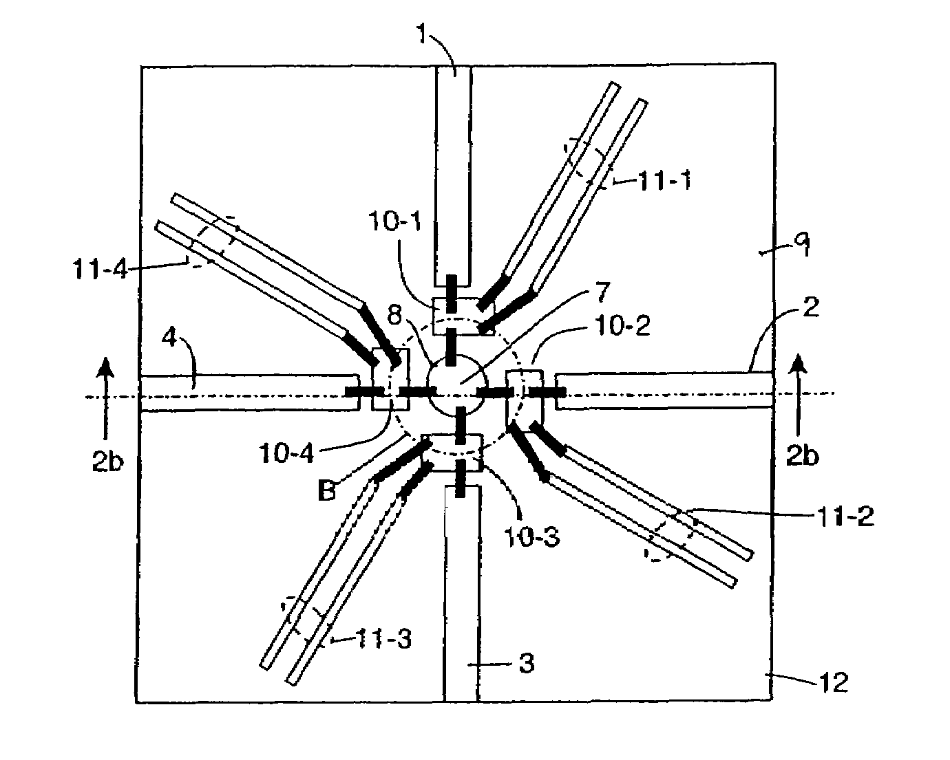
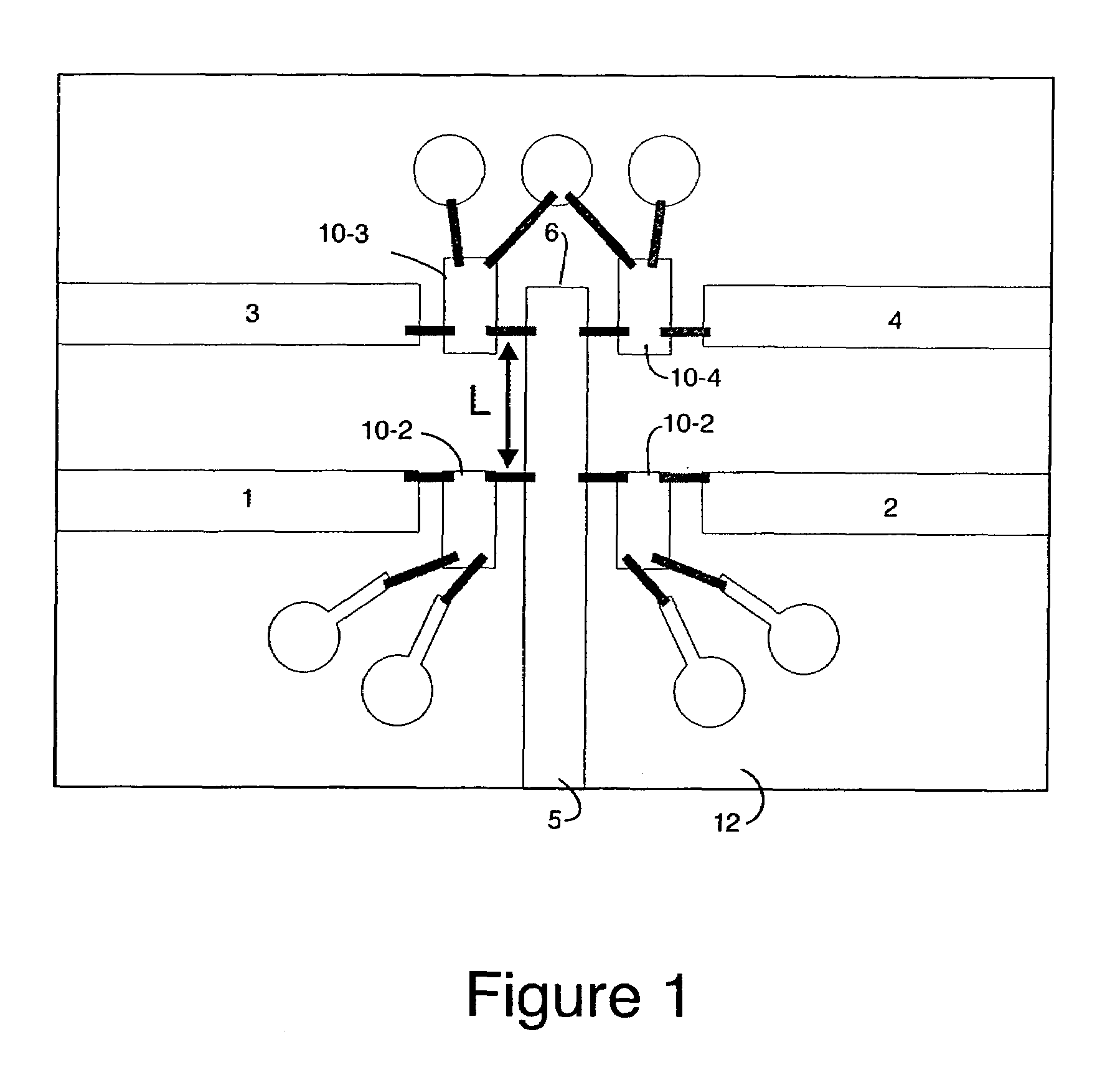
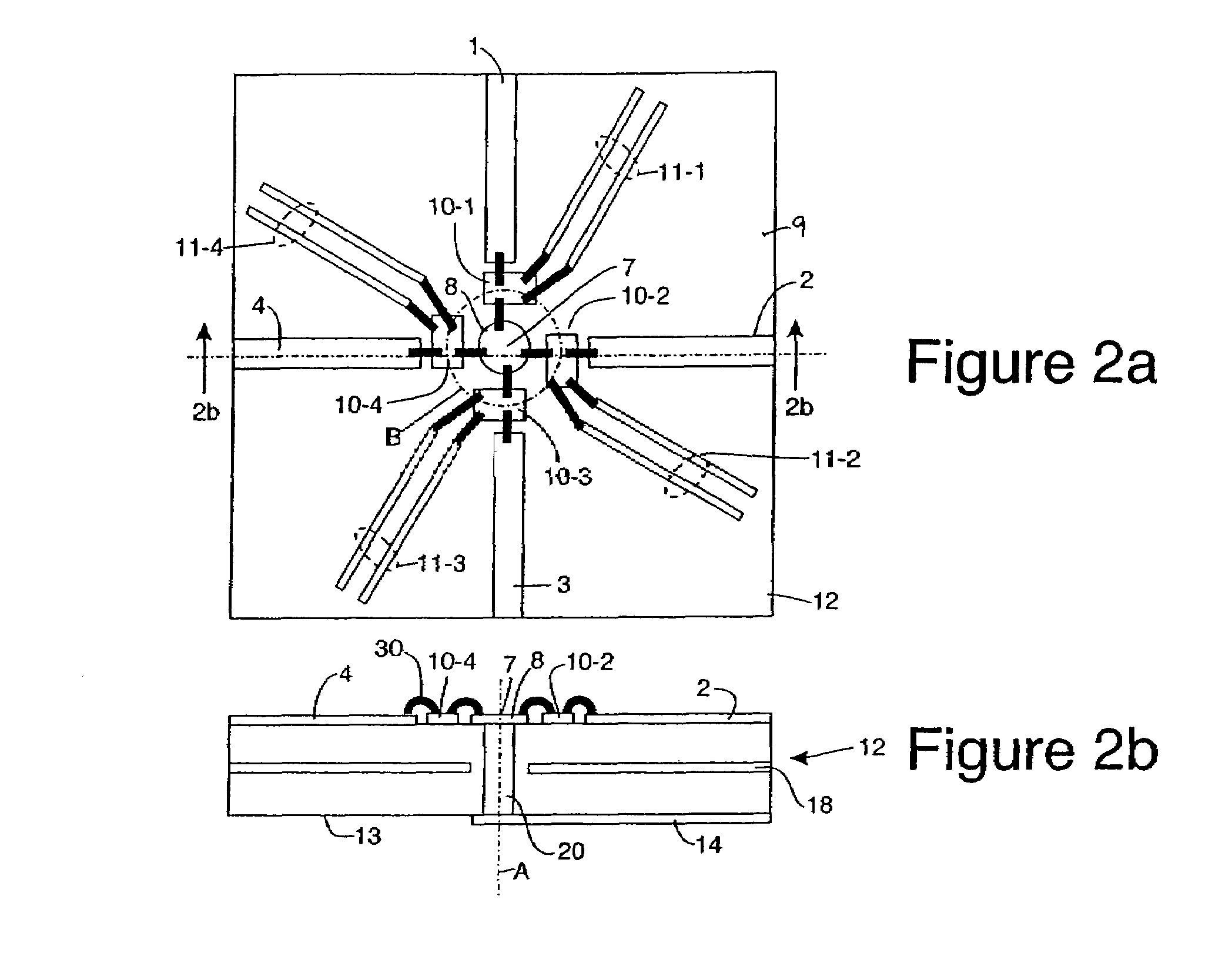
[0026]Recall FIG. 1 and the fact that this design poses a number of problems in terms of the impedances seen from the common port of the microstrip line 6 when the various ports 1-4 are switched on. One solution to this problem is shown in FIGS. 2a and 2b. The structure of FIGS. 2a and 2b preferably consists of a multi-layer printed circuit board 12, on which a common RF line 14 is formed on the bottom or back side 13 of the board 12, and is fed through a ground plane 18 by a metal plated via 20 to a central point 7 in the center of a 1×4 switch matrix of switches 10-1 through 10-4, which switches may be made as a hybrid on a common substrate (not shown) or which may be individually attached to surface 9. Switches 10-1 through 10-4 comprise a set of RF MEMS switches 10 (the numeral 10 when used without a dash and another numeral is used herein to refer to these RF MEMS switches in general as opposed to a particular switch). As will be seen, the number of switches 10 in the set can b...


PUM


Abstract

A switch arrangement comprises a plurality of MEMS switches arranged on a substrate about, and close to, a central point, each MEMS switch being disposed on a common imaginary circle centered on the central point. Additionally, and each MEMS switch is preferably spaced equidistantly along the circumference of the imaginary circle and within one quarter wavelength of the central point for frequencies in the passband of the switch arrangement. Connections are provided for connecting a RF port of each one of the MEMS switches with the central point.

Description

CROSS REFERENCE TO RELATED APPLICATION[0001]This application is a Continuation in Part of U.S. patent application Ser. No. 10 / 436,753 filed May 12, 2003, which application is incorporated herein by reference. This application and U.S. patent application Ser. No. 10 / 436,753 both claim the benefit of U.S. Provisional Patent Application No. 60 / 381,099 filed on May 15, 2002, which application is also incorporated herein by reference.TECHNICAL FIELD[0002]This invention relates to single-pole, multi-throw switches that are built using single-pole, single-throw devices combined in a hybrid circuit. The switches of this invention are symmetrically located around a central point which is a vertical via in a multi layer printed circuit board.BACKGROUND OF THE INVENTION AND CROSS REFERENCE TO RELATED APPLICATIONS[0003]This application incorporates by reference the disclosure of U.S. Provisional Patent Application Ser. No. 60 / 470,026 filed May 12, 2003 and entitled “RF MEMS Switch with Integrat...

Claims


Application Information

Patent Timeline
Patent Type & Authority Patents(United States)
IPC IPC(8): H01P1/10H01Q21/00H01P1/12H01P5/04H01Q13/08
CPCH01P1/10H01Q13/085H01P5/04H01P1/127H01Q3/24H01Q21/205
Inventor SIEVENPIPER, DANIEL F.
Owner HRL LAB
Why Eureka
Try Eureka