
Foot drying device

a drying device and foot technology, applied in the field of foot drying devices, can solve the problems of long treatment time, difficult treatment, long treatment time, etc., and achieve the effect of facilitating rapid and effective engagement with the user

Inactive Publication Date: 2007-10-09
ESPINOSA ROMAN
View PDF9 Cites 7 Cited by
  • Summary
  • Abstract
  • Description
  • Claims
  • Application Information

AI Technical Summary

Benefits of technology

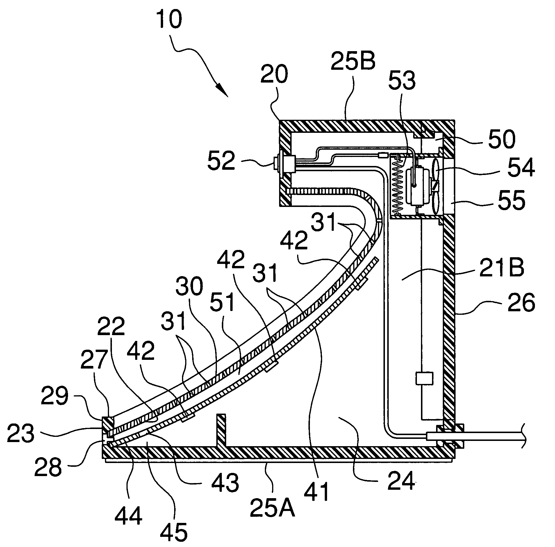
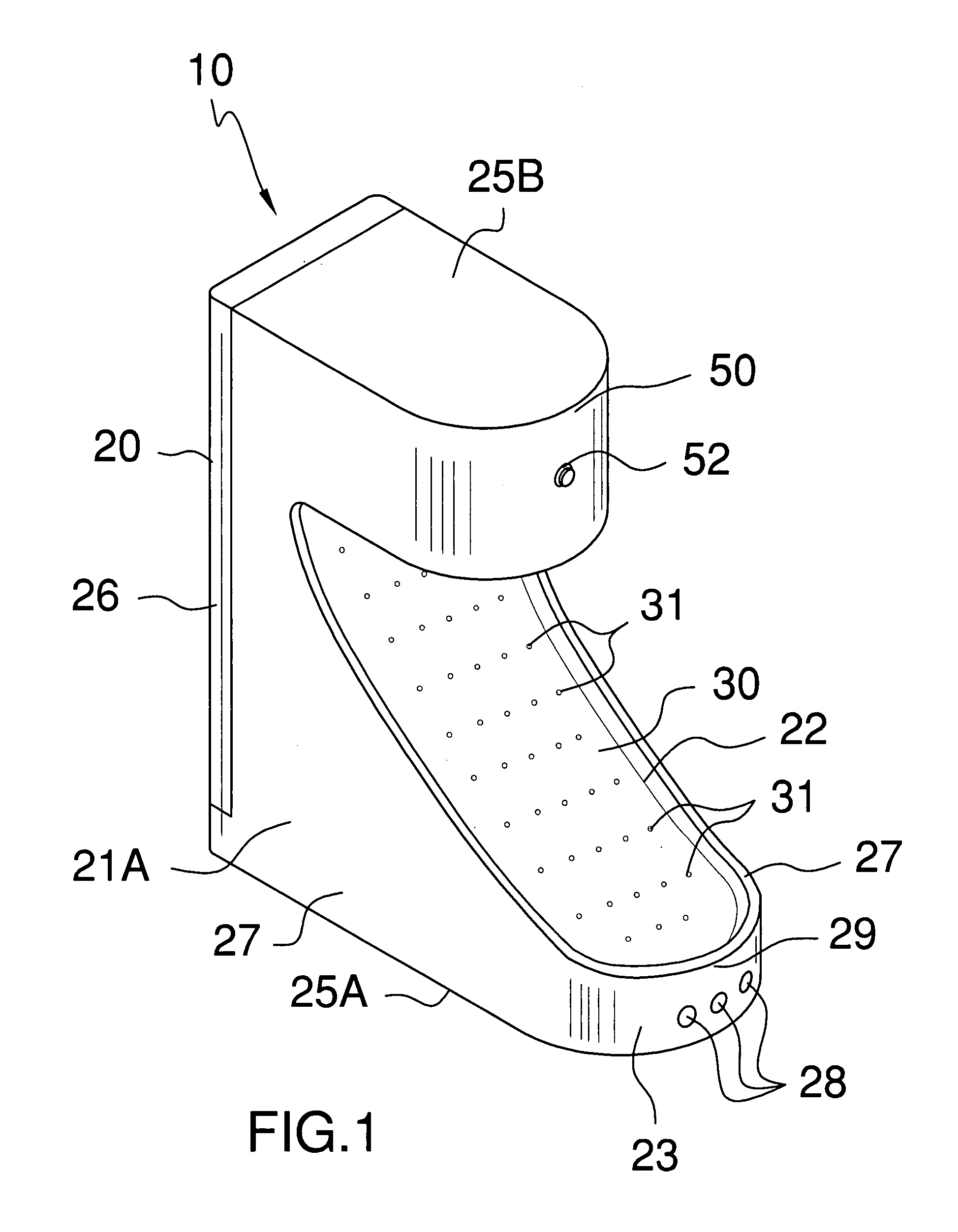
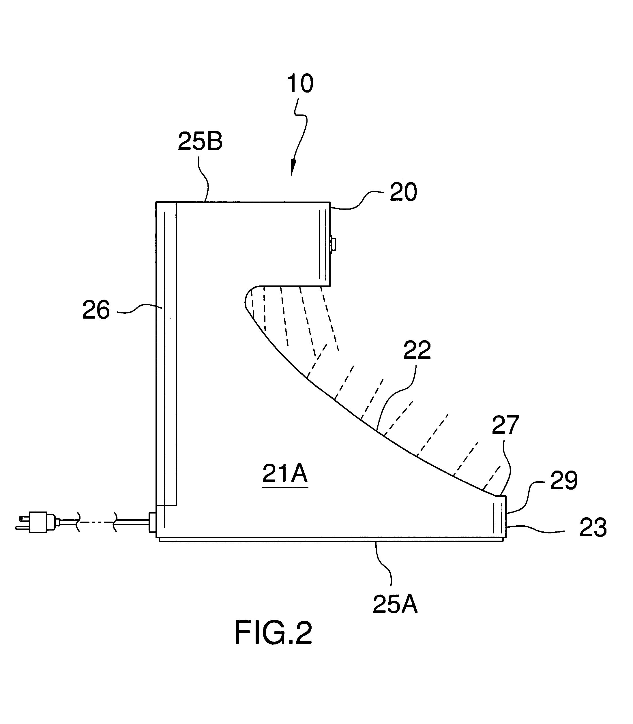
[0014]The foot-drying device includes a body including first and second vertically oriented sides extending upward from a ground surface. Such a body further includes an open front face distally sloping upward away from a front edge of the body. The body is hollow and forms a chamber that extends from a bottom surface to a top surface of the body. Such a body further has a rear panel hingedly coupled thereto for advantageously and effectively allowing the user to access the chamber without detaching the foot pad from the open front face.
[0016]A flexible foot pad is removably seated over the open front face. Such a foot pad is formed from non-corrosive material and further is provided with a plurality of apertures formed therein for effectively and conveniently draining water away from the user foot.

Problems solved by technology

The prevention and cure of athlete's foot (mycosis) and verrucas on the soles of the feet (two of the ten most common skin complaints in this field), require constant, lengthy and costly treatment by a dermatologist.
These infections recur frequently and are difficult to treat with conventional means based on creams, topical solutions of imidazolic derivatives, oral medication, etc., which, although effective, are long and relatively costly.
Although most individuals can take the drying of their feet for granted, there are some that find this task much more difficult than what it seems at face value.
For instance, a person suffering from severe back pain will find it rather difficult to bend over in attempt to reach their toes.
Similarly, a pregnant woman may also find that bending to reach her toes for drying purposes is not an easy task.
Unfortunately, airflow only passes over the soles of the user's feet, neglecting, for the most part, the upper portions and toes of the feet.
Thus the device does not perform a thorough drying job, especially when one considers that the areas between the toes are most susceptible to bacterial, viral and fungal growths.

Method used


Image

  • Foot drying device
  • Foot drying device
  • Foot drying device

Examples


Embodiment Construction

[0028]The present invention will now be described more fully hereinafter with reference to the accompanying drawings, in which a preferred embodiment of the invention is shown. This invention may, however, be embodied in many different forms and should not be construed as limited to the embodiment set forth herein. Rather, this embodiment is provided so that this application will be thorough and complete, and will fully convey the true scope of the invention to those skilled in the art. Like numbers refer to like elements throughout the figures.

[0029]The device of this invention is referred to generally in FIGS. 1-5 by the reference numeral 10 and is intended to provide a foot drying device. It should be understood that the device 10 may be used to dry many different types of body parts or other objects, and should not be limited in use to only drying one's feet.

[0030]Referring initially to FIGS. 1, 2, 3 and 4, the device 10 includes a body 20 including first 21A and second 21B vert...


PUM


Abstract

A foot-drying device includes a body including first and second vertical sides, and an open front face sloping upward away from a front edge thereof. The body is hollow, forming a chamber that extends from a bottom surface to a top surface thereof, and has a rear panel hingedly coupled thereto. A foot pad is seated over the open front face and is provided with apertures for draining water therethrough. A mechanism is included for diverting the water outwardly from the chamber as the water drips down through the apertures of the foot pad. A mechanism is included for introducing heated air into the chamber such that the heated air is quickly engaged with the user foot. The heated air is evenly discharged from the apertures such that the water on the user foot is completely expelled away therefrom. The air heating mechanism is disposed above the water diverting mechanism.

Description

CROSS REFERENCE TO RELATED APPLICATIONS[0001]Not Applicable.STATEMENT REGARDING FEDERALLY SPONSORED RESEARCH OR DEVELOPMENT[0002]Not Applicable.REFERENCE TO A MICROFICHE APPENDIX[0003]Not Applicable.BACKGROUND OF THE INVENTION[0004]1. Technical Field[0005]This invention relates to drying devices and, more particularly, to a foot drying device for quickly drying a user foot when same has become wet.[0006]2. Prior Art[0007]The prevention and cure of athlete's foot (mycosis) and verrucas on the soles of the feet (two of the ten most common skin complaints in this field), require constant, lengthy and costly treatment by a dermatologist. Athlete's foot and verrucas are very easily transmitted, given the physical and biochemical characteristics of the microorganisms that cause them (fungi and viruses of this nature develop in the presence of moisture). These infections recur frequently and are difficult to treat with conventional means based on creams, topical solutions of imidazolic der...

Claims


Application Information

Patent Timeline
Patent Type & Authority Patents(United States)
IPC IPC(8): F26B19/00
CPCA47K10/48
Inventor ESPINOSA, ROMAN
Owner ESPINOSA ROMAN
Learn More