
Rotatable vehicle rim cleaning device

a rim cleaning and rotatable technology, applied in the field of cleaning devices, can solve the problems of requiring additional equipment, affecting the use of individual devices, and purchasing each of these specialized devices at significant combined costs, and achieve the effect of convenient access for users and sufficient grip of brushes

Inactive Publication Date: 2008-04-15
BEIERMANN DAVID M
View PDF23 Cites 31 Cited by
  • Summary
  • Abstract
  • Description
  • Claims
  • Application Information

AI Technical Summary

Benefits of technology

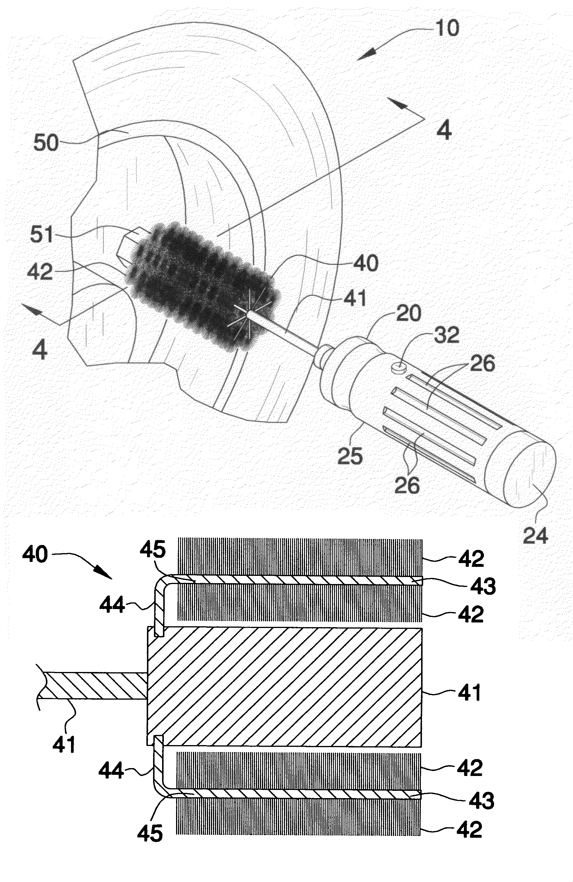
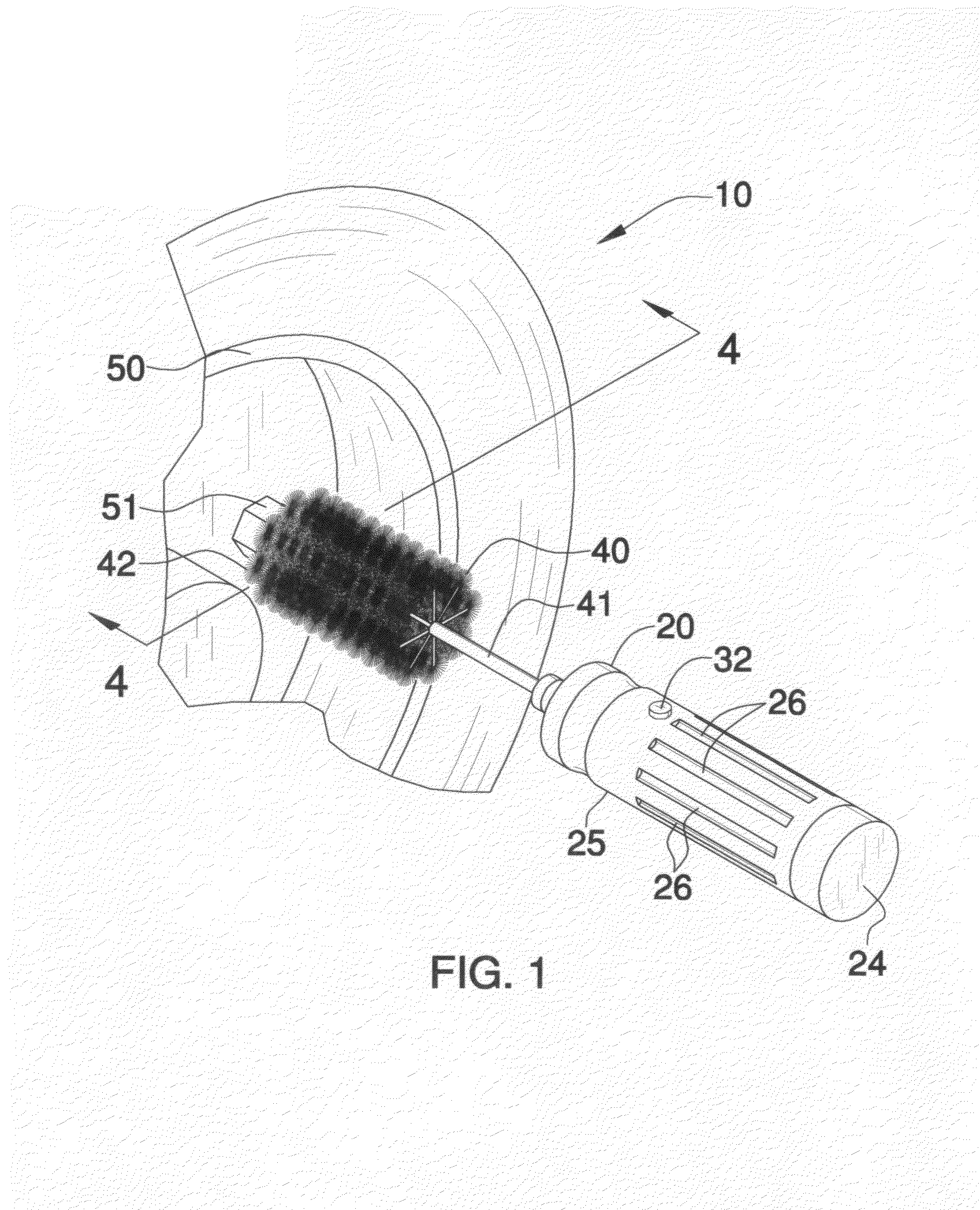
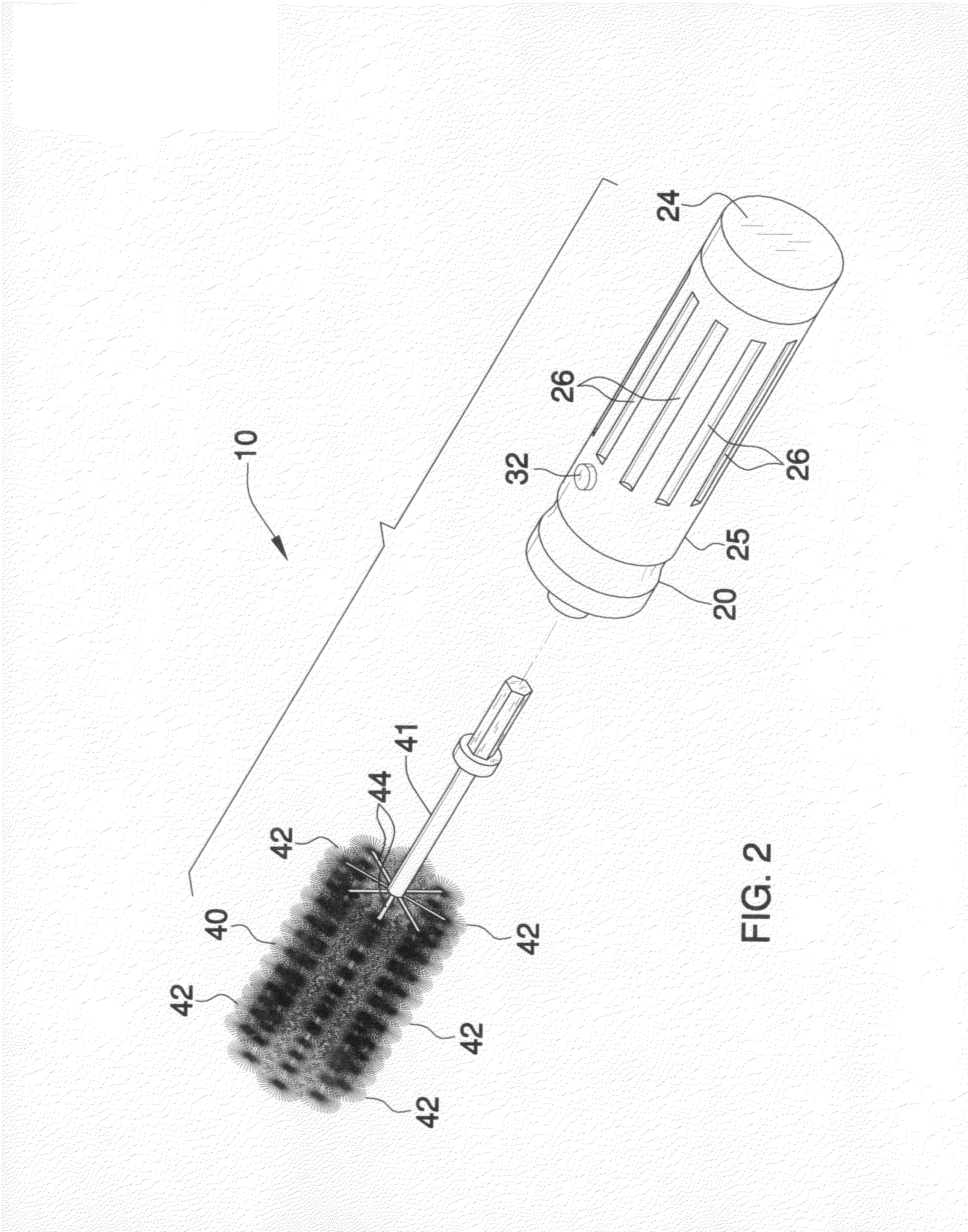
[0011]The brush includes a hollow handle section having a plurality of adjacent internal compartments and a substantially cylindrical shape. Such a handle section is provided with a centrally disposed longitudinal axis further having proximal and distal end portions oppositely spaced along the axis. The handle section includes a cap removably attachable to the proximal end portion for conveniently allowing a user to access one of the compartments thereof. Such a handle further has an outer surface provided with a plurality of linear grooves extending substantially parallel to the axis for advantageously assisting an operator to maintain a sufficient grip of the brush. The distal end portion is provided with an outlet in fluid communication with the compartments.

Problems solved by technology

However, in order to have the benefit of a multiplicity of these specialized cleaning devices, one must purchase each of these specialized devices at significant combined cost.
Still further, maintaining each of the devices and toting the devices around during cleaning chores poses further challenges to the use of these individual devices.

Method used


Image

  • Rotatable vehicle rim cleaning device
  • Rotatable vehicle rim cleaning device
  • Rotatable vehicle rim cleaning device

Examples


Embodiment Construction

[0025]The present invention will now be described more fully hereinafter with reference to the accompanying drawings, in which preferred embodiments of the invention are shown. This invention may, however, be embodied in many different forms and should not be construed as limited to the embodiments set forth herein. Rather, these embodiments are provided so that this application will be thorough and complete, and will fully convey the true scope of the invention to those skilled in the art. Like numbers refer to like elements throughout the figures and prime and double prime numbers refer to alternate embodiments of such elements.

[0026]The device of this invention is referred to generally in FIGS. 1-8 by the reference numeral 10 and is intended to provide a rotatable vehicle rim cleaning device. It should be understood that the device 10 may be used / adapted to clean many different types of surfaces and should not be limited to only vehicle rims.

[0027]Referring initially to FIG. 1, t...


PUM


Abstract

A hand-operable brush for cleaning the crevices of vehicle rims includes a handle having adjacent internal compartments and proximal and distal ends. The handle has an outer surface with linear grooves for assisting an operator to maintain a sufficient grip. The distal end is provided with an outlet in fluid communication with the compartments. A variable speed motor is disposed within one of the compartments and includes a drive shaft and a switch connected thereto. The device also includes a cleaning section including a driven shaft operable via the motor and having bristles extending away therefrom. A coupling member is positioned adjacent to the distal end and provided with isolated channels for receiving the drive shaft and the driven shaft. A power supply source including a plurality of batteries is housed within one compartment and is electrically coupled to the motor.

Description

CROSS REFERENCE TO RELATED APPLICATIONS[0001]Not Applicable.STATEMENT REGARDING FEDERALLY SPONSORED RESEARCH OR DEVELOPMENT[0002]Not Applicable.REFERENCE TO A MICROFICHE APPENDIX[0003]Not Applicable.BACKGROUND OF THE INVENTION[0004]1. Technical Field[0005]This invention relates to a cleaning device and, more particularly, to a portable vehicle rim cleaning device.[0006]2. Prior Art[0007]As is well-known in the art, many devices and tools exist for assisting in the cleaning of car rims, mag-wheels, and the like. Arising from the inherent problems and inadequacies associated with a common sponge or washcloth, these devices have been developed to solve a variety of particular problems associated with the cleaning of these objects that have complex and intricate shapes.[0008]More specifically, cleaning devices such as brush cleaning devices for single specialized purposes are known in the art. However, in order to have the benefit of a multiplicity of these specialized cleaning devices,...

Claims


Application Information

Patent Timeline
Patent Type & Authority Patents(United States)
IPC IPC(8): A46B13/02B08B9/023
CPCA46B13/001A46B13/02B08B1/04B08B9/00B60S3/042A46B2200/3013A46B2200/3046B08B1/32
Inventor BEIERMANN, DAVID M.
Owner BEIERMANN DAVID M
Learn More