Control pin

a technology of control pins and control pins, which is applied in the field of control pins, can solve the problems of low maintenance requirements, high hardness of control pins made of laminated composite ceramic materials, and high maintenance requirements, so as to prevent the breakage of control pins and the blocking of pouring spouts, reduce erosion, and safely remove and replace.

Inactive Publication Date: 2007-10-09
PYROTECK INC
View PDF11 Cites 9 Cited by
  • Summary
  • Abstract
  • Description
  • Claims
  • Application Information

AI Technical Summary

Benefits of technology

[0009]A control pin made of a laminated composite ceramic material is extremely tough owing to the presence of the reinforcing fabric, which prevents cracks propagating through the material. Breakage of the control pin and blocking of the pouring spout is therefore prevented throughout the normal designed lifespan of the control pin. If, after excessive usage and degradation of the reinforcing fabric, the control pin does break, the failsafe element holds the broken parts together, allowing the control pin to be safely withdrawn and replaced.
[0010]The control pin includes a wear-resistant tip at the lower end of the elongate body member, to reduce erosion by the liquid metal and wear from contact with the spout.
[0011]The composite ceramic material also has good thermal shock characteristics and is not wetted or attacked by liquid aluminium. A control pin made of this material therefore has a long life and a low maintenance requirement.
[0012]A control pin made of the composite ceramic material can also have a low heat capacity and so does not have to be pre-heated prior to commencement of the metal pouring operation. This greatly simplifies the pouring operation and provides substantial cost savings and safety benefits.
[0020]Advantageously, the control pin includes a non-stick surface coating, which may include boron nitride, to reduce wetting by the liquid metal and reduce or prevent the depositing of a skin or skull of metal on the surface of the control pin. Although the provision of a non-stick coating is preferred, that coating does not have to be reapplied as frequently as with control pins made of other some materials such as DFS, since the composite ceramic material of the pin body is naturally non-wetted.
[0022]The elongate body member is preferably at least partially hollow. This reduces the heat capacity of the pin, so that it heats rapidly on contact with the liquid metal, without causing the metal to freeze. It is particularly advantageous for the lower portion of the control pin, which is immersed in the liquid metal, to be hollow. The elongate body member may include a circumferential wall having a wall thickness in the range 1-10 mm, preferably approximately 5 mm, to provide a low heat capacity.

Problems solved by technology

A control pin made of a laminated composite ceramic material is extremely tough owing to the presence of the reinforcing fabric, which prevents cracks propagating through the material.
A control pin made of this material therefore has a long life and a low maintenance requirement.

Method used


Image

  • Control pin
  • Control pin
  • Control pin

Examples


Embodiment Construction

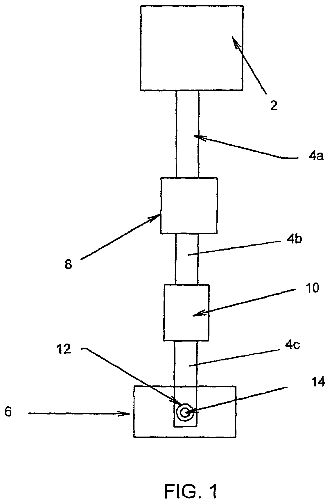
[0039]A typical aluminium casting installation is shown schematically in FIG. 1 and includes a furnace 2, from which molten metal flows through a set of launders 4a, 4b, 4c (or troughs) to a mould 6, which may for example be a direct chill mould. Between the furnace 2 and the mould 6 various additional metal processing units may be provided including, for example, a degassing unit 8 and a filter unit 10. Metal flows from the last launder 4c into the mould 6 through a down spout 12, the flow through the spout being controlled by a control pin 14.

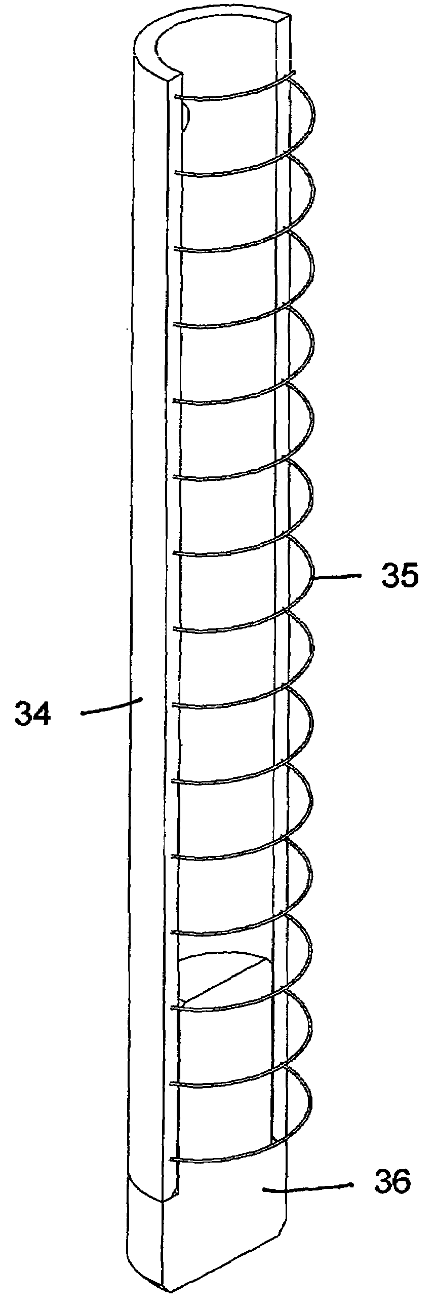
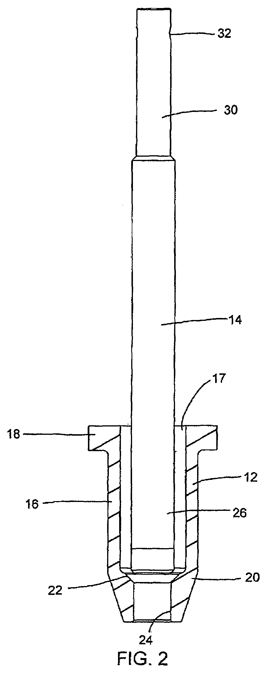
[0040]The down spout 12 and the associated control pin 14 are shown in more detail in FIG. 2. The down spout 12 is made of a refractory material such as dense fused silica (DFS) and is conventional in design. The spout is tubular, having a cylindrical wall 16 with an axial bore 17 and an outwardly extending flange 18 at its upper end. The lower part 20 of the spout has a frusto-conical external shape and internally has a frusto-conical seat 2...


PUM

PropertyMeasurementUnit
thicknessaaaaaaaaaa
densityaaaaaaaaaa
densityaaaaaaaaaa

Abstract

A control pin for controlling the flow of liquid metal in a casting process includes an elongate body member, the body member being made at least partially of a composite ceramic material that includes a fibrous reinforcing material embedded within a ceramic matrix, and a failsafe element embedded within the composite ceramic material.

Description

CROSS-REFERENCE TO RELATED APPLICATIONS[0001]This application claims priority under 35 U.S.C. § 119(a)-(d) to Great Britain Patent Application No. 0512285.8, filed Jun. 16, 2005, the entire contents of which are incorporated herein by reference.FIELD OF THE INVENTION[0002]The present invention relates to a control pin for controlling the flow of liquid metal in a casting process. In particular, but not exclusively, it relates to a control pin for controlling the flow of nonferrous liquid metals such as aluminium and zinc.BACKGROUND OF THE INVENTION[0003]A typical metal casting process is described in U.S. Pat. No. 3,111,732. In that process, liquid metal is poured through a spout (or “underpour outlet”) into a mould, where the metal freezes to form a billet or slab. The flow of metal through the spout is controlled by a control pin (or “flow regulator”) that is located within the spout. The control pin may be raised to increase the rate of flow of metal through the spout, or lowered...

Claims


Application Information

Patent Timeline
Patent Type & Authority Patents(United States)
IPC IPC(8): B22D11/10B22D41/18
CPCB22D41/18
Inventor VINCENT, MARK
Owner PYROTECK INC
Why Eureka
Try Eureka