Fluid mixing apparatus

a technology of mixing apparatus and flue, which is applied in the direction of mixing machine, rotary mixing machine, shaking/oscillating/vibrating machine, etc., and can solve problems such as adverse effects on economies

Inactive Publication Date: 2007-10-09
ENERSAVE FLUID MIXERS
View PDF28 Cites 5 Cited by
  • Summary
  • Abstract
  • Description
  • Claims
  • Application Information

AI Technical Summary

Problems solved by technology

However, the general configurations noted above have been found to provide relatively economical results, and significant variations therefrom can impact adversely upon economies.
Specifically, the relatively large motors employed are required to drive the sturdy (and therefore heavy) rotary mixers and shafts that are needed to withstand the torques caused by rotation; lower power motors would demand either lower blade speed or smaller blades, with consequent impacts upon mixing and transfer efficiency.

Method used


Image

  • Fluid mixing apparatus
  • Fluid mixing apparatus
  • Fluid mixing apparatus

Examples


example 1

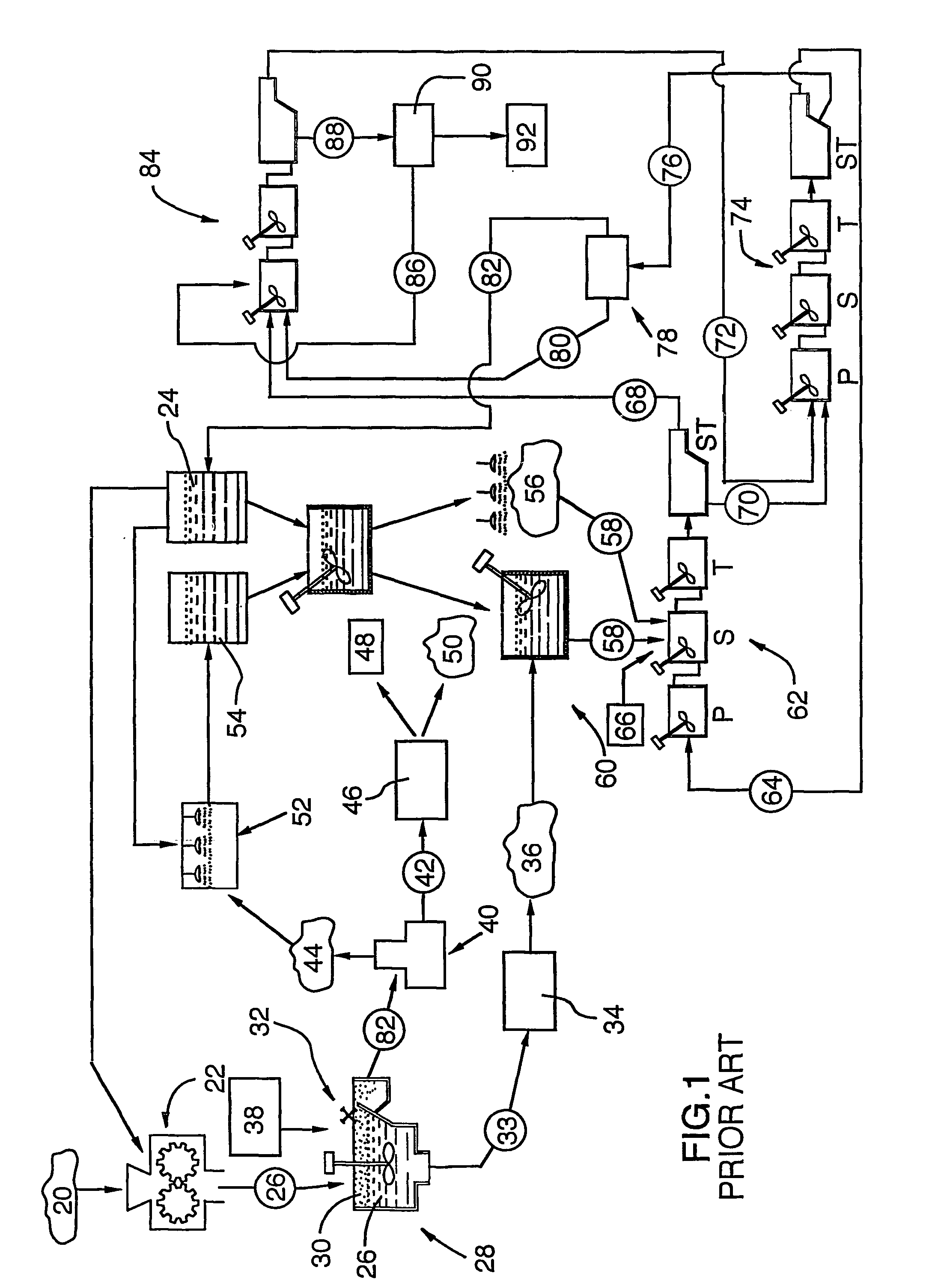
[0081]In the known application of the SXEW process previously described, samples were taken from the outfall of each of the primary vessel; secondary vessel; tertiary vessel and settling tank of a respective secondary extraction unit (A) and permitted to separate.

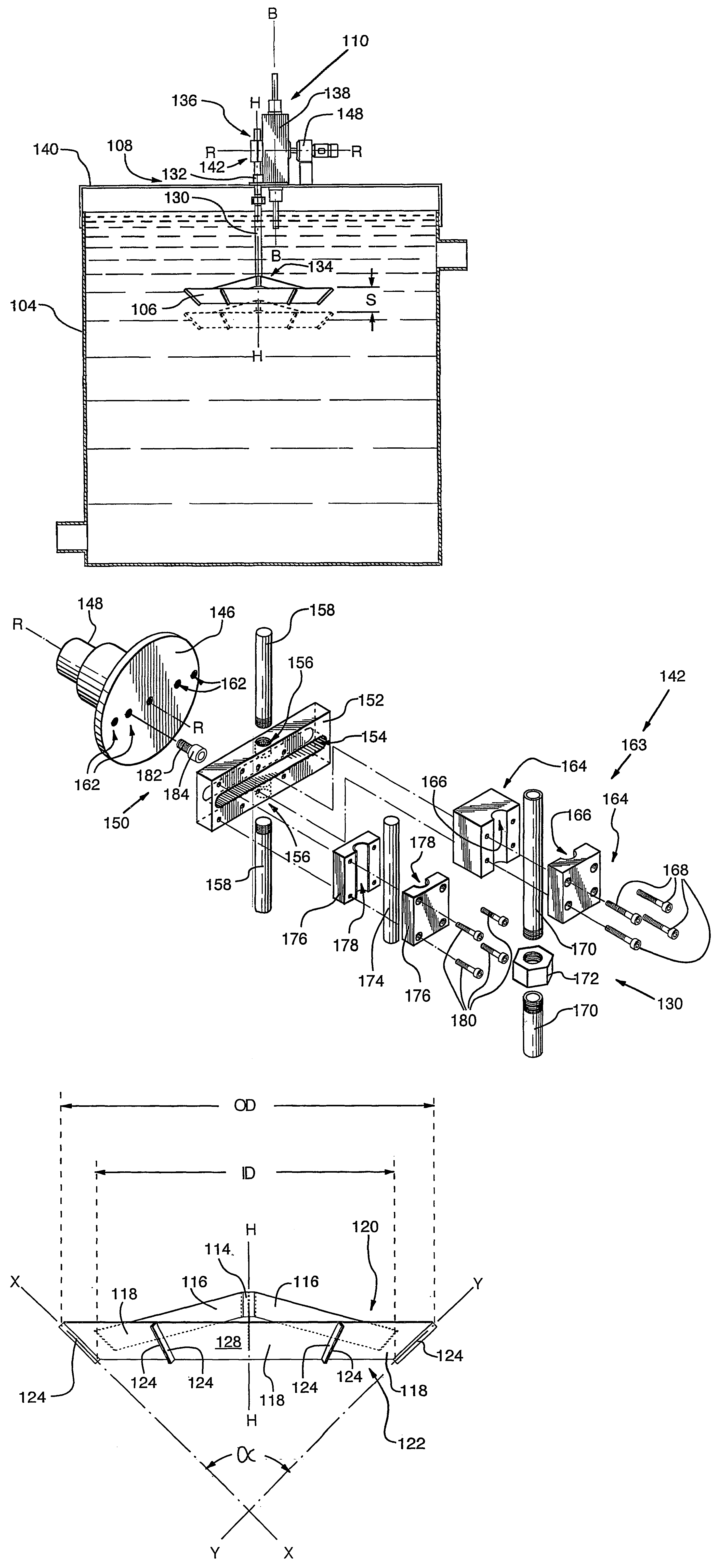
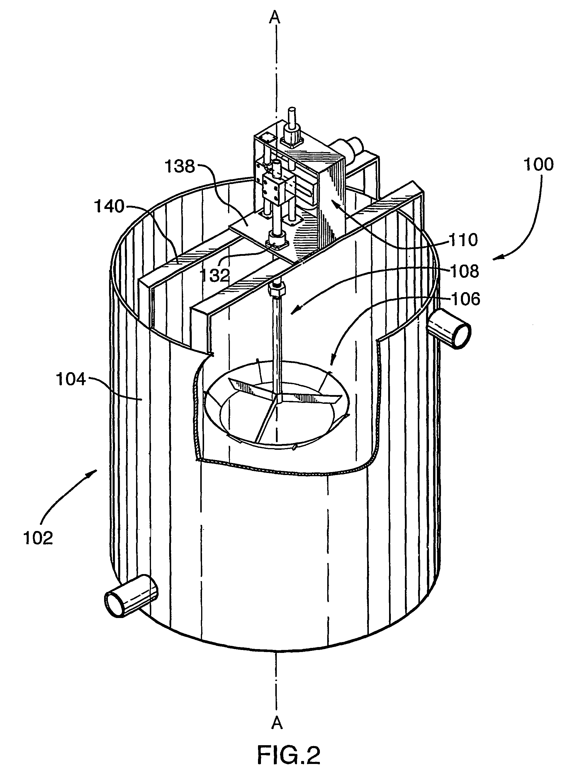
[0082]In a parallel secondary extraction unit (B) (ie processing a pregnant leachate of substantially identical composition), a mixing apparatus in accordance with the present invention (OD=60; ID=40; α=120°; S=10; T=0.0333, driven by a 2 hp motor) was substituted for the rotary mixer in the secondary mixing vessel, and samples were again taken from the outfall from each of the primary, second and tertiary mixing vessels, and from the settling tank, and permitted to separate.

[0083]Copper concentration (g / l) was measured in the organic component of each sample, as follows:

[0084]

(A)(B) [30 cpm]Cu (g / l)Cu (g / l)Primary mixing vessel2.012.01Secondary mixing vessel2.062.06Tertiary mixing vessel2.122.13Settling tank2.142.13

[0085]A...


PUM


Abstract

A mixer apparatus for use with a vessel centered about a longitudinal axis is disclosed. The mixer has a tubular blade which: defines a central head axis; has a first end and a second end spaced from the first end along the head axis; and tapers from the first end to the second end. The outer surface of the blade and the second end define an inside blade diameter “ID” and the outer surface of the blade and the first end define an outside blade diameter “OD”. The blade is positioned within and coaxial to the vessel. A scotch yoke, operatively connected to the blade by a shaft, effects reciprocating longitudinal movement of the blade through a stroke “S”, with a duration “T” for each stroke, wherein 175≲0.36×OD2 / ID2×S / T≲250 when OD, ID and S are expressed in inches, and T is expressed in minutes.

Description

TECHNICAL FIELD[0001]The present invention generally relates to the field of mineral ore processing, and more particularly, to a mixing apparatus and to uses thereof in the separation of minerals from mineral-bearing ores.BACKGROUND OF THE ART[0002]Processes are known in the prior art which provide for the separation of minerals from mineral-bearing ores.[0003]For example, in known processes used for the separation of copper from copper-bearing ores, illustrated diagrammatically in FIG. 1, non-oxidized ores 20 (which might contain as little as 0.5% copper, and typically contain iron sulfides) are processed in a crusher 22, with water 24, to form a slurry 26. The slurry 26 is then transferred to a flotation cell 28, and subjected to physical action, specifically, air sparging and mixing. As a result of the physical action, a substantial portion of the copper value in the slurry 26 rises to the surface of the flotation cell 28 as a froth 30, and is skimmed therefrom by a paddle mechan...

Claims


Application Information

Patent Timeline
Patent Type & Authority Patents(United States)
IPC IPC(8): B01F11/00B01F15/00
CPCB01F11/0082B01F11/0091B01F15/00467B01F2215/0431B01F2215/0409B01F2215/0422B01F31/441B01F31/449B01F35/325
Inventor HAUGHTON, GARYBEHR, MARTINOSTROWSKI, TOM
Owner ENERSAVE FLUID MIXERS
Why Eureka
Try Eureka