Motorcycle foot peg "cradle mount bracket"

a foot peg and motorcycle technology, applied in the field of motorcycle foot peg mounting, can solve problems such as flexing the frame, and achieve the effects of reducing flex, adding reliability, and adding to operator's confiden

Inactive Publication Date: 2007-10-16
ROGOZIENSKI JOHN
View PDF4 Cites 3 Cited by
  • Summary
  • Abstract
  • Description
  • Claims
  • Application Information

AI Technical Summary

Benefits of technology

[0009]The invention provides a foot peg assy mount for motorcycles that assists the motorcycle riders to lessen flex and add reliability in the foot peg assy. This will add to the operator's confidence and reduce fatigue and therefore retain a higher level of concentration.

Problems solved by technology

Frequently, however, the loads of the engine combined with rider weight will often flex the frame and movement will be felt as the unstableness is at the rider's feet.

Method used


Image

  • Motorcycle foot peg "cradle mount bracket"
  • Motorcycle foot peg "cradle mount bracket"
  • Motorcycle foot peg "cradle mount bracket"

Examples


Embodiment Construction

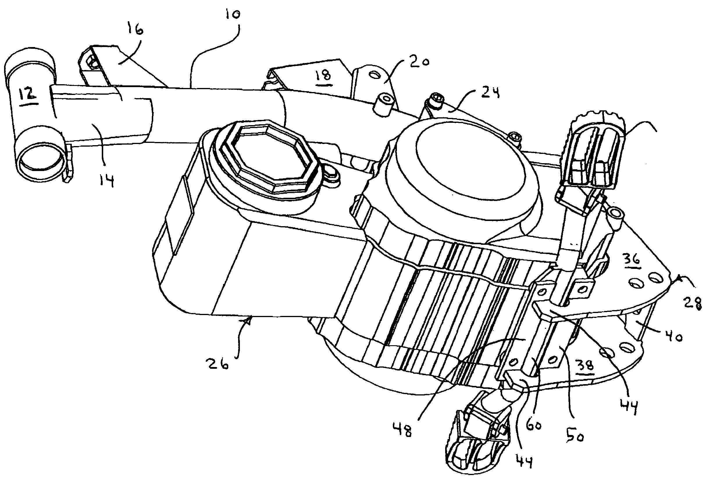
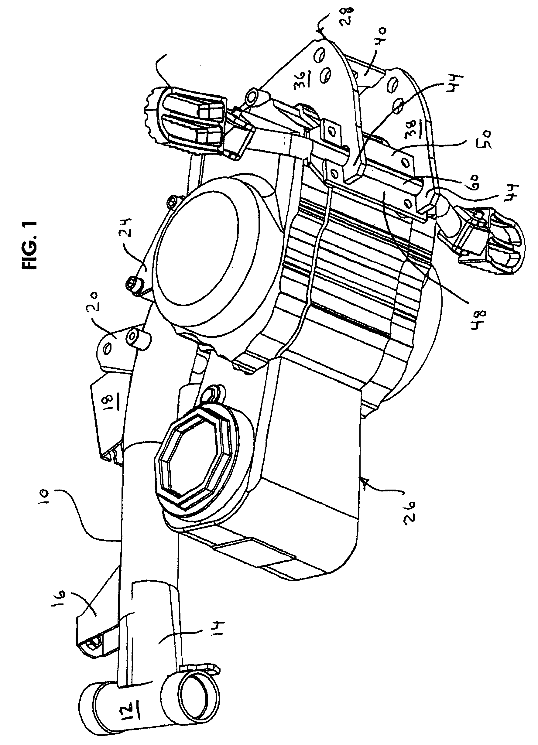
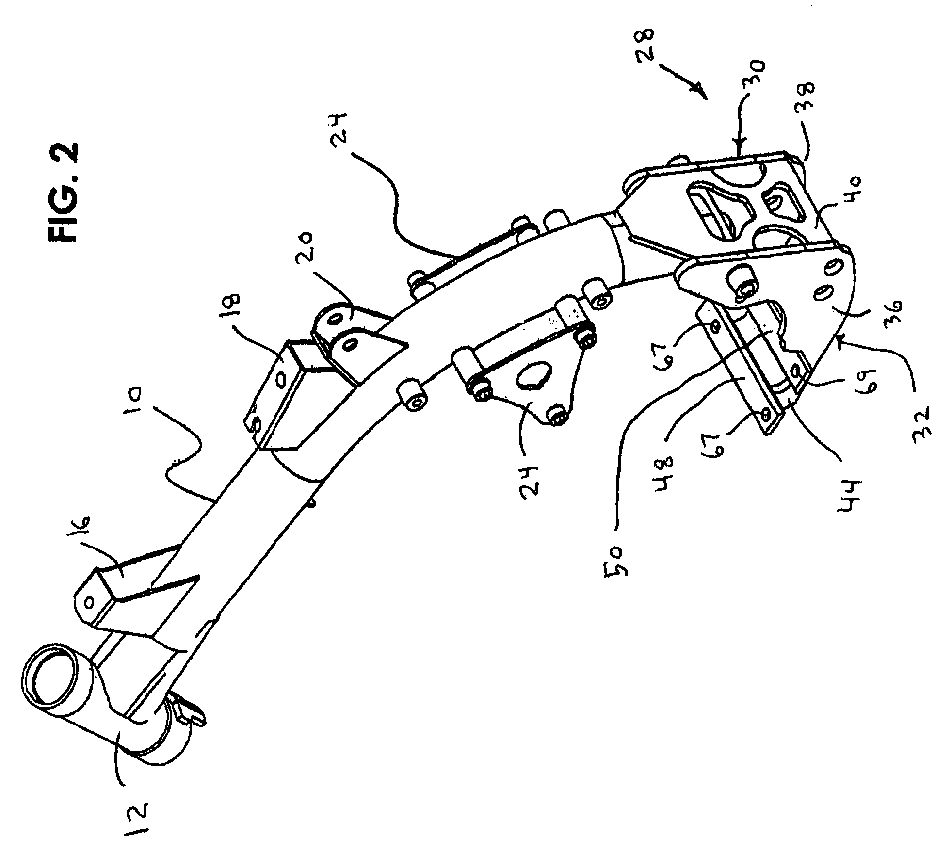
[0016]The invention will now be described by referring to FIGS. 1–4 of the drawing. FIG. 1 is bottom perpective view illustrating tubular main frame 10 of a motorcycle having a head fork tube 12 connected to its front end. A gusset 14 on each lateral side adds structural integrity to the connection between main frame 10 and head fork tube 12.

[0017]A fuel tank mount 16 is secured to the top surface of tubular main tube 10. A seat mounting bracket 18 is also secured to the top surface of tubular main frame tube 10. A shock mount 20 is connected to the top surface of main frame tube 10. Each side of main frame tube 10 has a pair of sub-frame mounts 22. Also each side of tubular main frame 10 has a motorcycle engine hangar bracket 24.

[0018]A motorcycle engine 26 has its top end supportably connected to the respective motorcycle engine hangar brackets 24. The bottom end of motorcycle engine 26 is attached to cradle bracket 28. Cradle bracket 28 has an upright oriented attachment portion ...


PUM


Abstract

A motorcycle foot peg having a body portion adapted to bear the weight of a rider. The body portion will fold up about the mounting shaft, which is connected to the frame of the motorcycle by way of cradle mount brackets that sandwich the mounting shaft between engine and brackets. The mounting shaft support tabs with holes that correspond to the engine mounting threaded holes. The cradle mount brackets have corresponding holes to align with engine and mounting shaft tabs. The cradle mount brackets, mounting shaft and engine, will support the rider's weight on the foot peg load.

Description

BACKGROUND OF THE INVENTION[0001]1. Technical Field of the Invention[0002]This invention relates to motorcycles and more particularly to an improvement in foot peg mounting for motorcycles. In this specification, reference to motorcycles includes both two and three wheeled motorcycles and also four wheeled all terrain vehicles, which are ridden in a manner similar to motor cycles.[0003]2. Description of the Prior Art[0004]As is well know, most motorcycle assemblies include a frame having a seat on which a rider sits in a straddle fashion. A pair of foot pegs are carried at the lower end of the frame at opposite sides thereof for the rider to place his feet when riding. Frequently, controls for operating certain components of the motorcycle, such as a rear wheel brake or gearshift, is located in close proximity to the foot pegs. This allows the operator to foot activate the said controls when desirable. It is common for motorcycle foot pegs to vary in appearance depending on intended...

Claims


Application Information

Patent Timeline
Patent Type & Authority Patents(United States)
IPC IPC(8): B62J25/00
CPCB62K11/06B62J25/00B62J25/04
Inventor ROGOZIENSKI, JOHN
Owner ROGOZIENSKI JOHN
Why Eureka
Try Eureka