Optimum Radio Communication Method With Radio Frame Variable Control And Radio Communication System Using The Same

a radio communication system and variable control technology, applied in multiplex communication, orthogonal multiplex, transmission monitoring, etc., can solve the problems of difficult to respond appropriately in a mobile communication system, and achieve flexible high-speed data transmission, good receive quality, and control channel symbols can be reduced flexibly.

Inactive Publication Date: 2012-03-15
FUJITSU LTD
View PDF8 Cites 13 Cited by
  • Summary
  • Abstract
  • Description
  • Claims
  • Application Information

AI Technical Summary

Benefits of technology

[0016]Therefore it is an object of the present invention to provide an optimum radio communication method by a radio frame variable control which can more flexibly decrease the distributed number of not only the pilot channel symbols, but also the control channel symbols, and a radio communication system using the method.
[0020]Because of the above mentioned characteristics of the present invention, not only pilot channel symbols, but also control channel symbols can be flexibly decreased for a reception side apparatus of which receive quality is good. Therefore the decreased channel symbols can be replaced with data symbols, which allows more flexible high-speed data transmission.

Problems solved by technology

If such a fixed frame format is used, however, it is difficult to respond appropriately in a mobile communication system, even if the line speed could be increased depending on the line status between the transmission side apparatus (base station) and the reception side apparatus (mobile terminal).

Method used


Image

  • Optimum Radio Communication Method With Radio Frame Variable Control And Radio Communication System Using The Same
  • Optimum Radio Communication Method With Radio Frame Variable Control And Radio Communication System Using The Same
  • Optimum Radio Communication Method With Radio Frame Variable Control And Radio Communication System Using The Same

Examples


Embodiment Construction

[0033]Embodiments of the present invention will now be described with reference to the drawings. The embodiments are for assisting the understanding of the present invention, and not for limiting the application of the present invention to these embodiments.

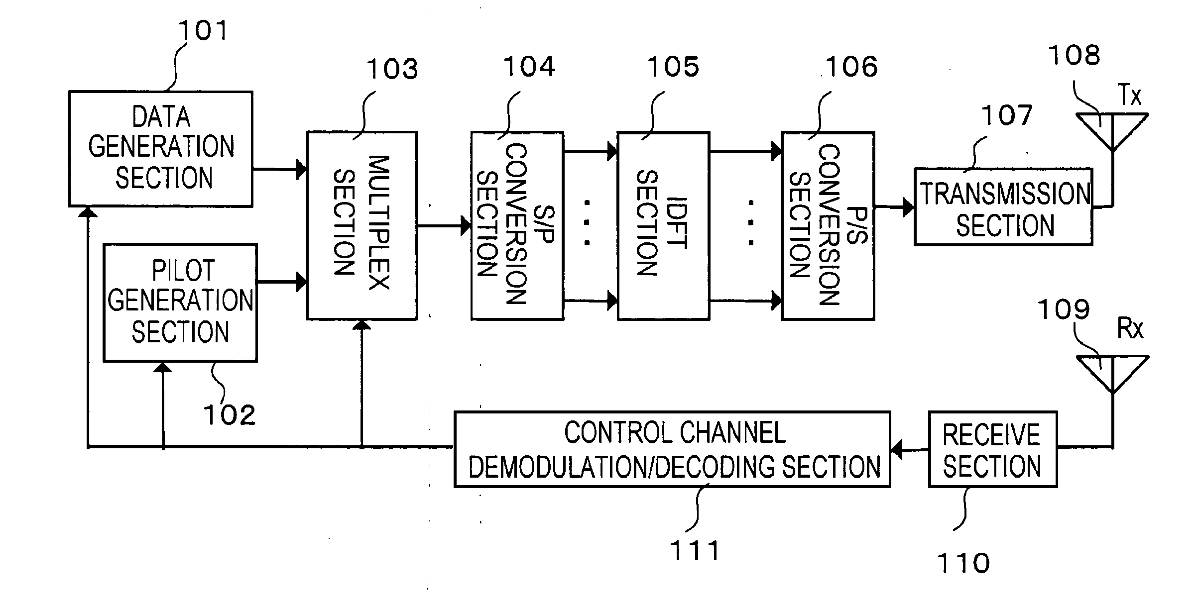
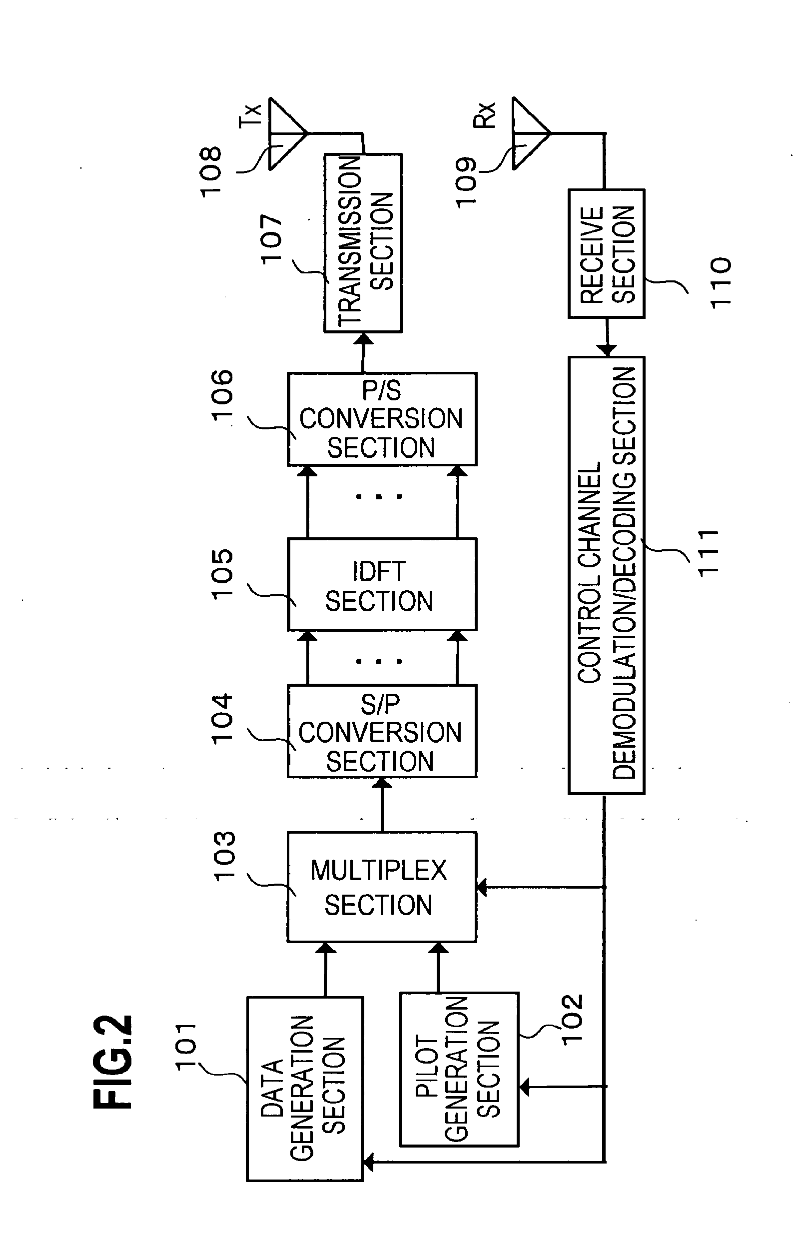
[0034]FIG. 2 is a block diagram depicting a general configuration of a transmission side apparatus of the first embodiment, where an optimum radio communication method based on a radio frame variable control according to the present invention is applied. FIG. 3 is a block diagram depicting a general configuration of a reception side apparatus corresponding to the transmission side apparatus in FIG. 2.

[0035]As an embodiment, the transmission side apparatus in FIG. 2 is a base station apparatus, and the reception side apparatus in FIG. 3 is a mobile terminal.

[0036]FIG. 4 is a flow chart depicting a processing sequence between the transmission side apparatus and the reception side apparatus according to a first embodiment.

[0037]In F...


PUM


Abstract

A radio communication system includes a transmission apparatus configured to transmit data using a radio frame formed in one time block, to which a plurality of continuous or discontinuous frequency areas are assigned, and a reception apparatus configured to receive the data transmitted from the transmission apparatus by using the radio frame. The transmission apparatus transmits to the reception apparatus a radio frame provided in the beginning of the radio frame with a pilot which is a known signal used for measurement of reception quality and a control signal used for the control of demodulation at the reception apparatus. The reception apparatus transmits reception quality information concerning reception quality measured by the pilot, and the transmission apparatus performs a transmission process by using a radio frame format which does not include control information for the reception apparatus which has transmitted the reception quality information.

Description

CROSS-REFERENCE TO RELATED APPLICATIONS[0001]This application is a divisional of U.S. patent application Ser. No. 11 / 984,964, filed Nov. 26, 2007, which is based upon and claims the benefit of priority from the prior Japanese Patent Application No. 2006-322269, filed on Nov. 29, 2006, the entire contents of both of which are incorporated herein by reference.BACKGROUND OF THE INVENTION[0002]1. Field of the Invention[0003]The present invention relates to an optimum radio communication method with a radio frame variable control and a radio communication system using the method.[0004]2. Description of the Related Art[0005]FIG. 1 is a diagram depicting a radio format of which specification is standardized by 3GPP (Third Generation Partnership Project) as an international standard of a third generation high-speed mobile communication system.[0006]In FIG. 1, only the n-th frame is shown. This means that the (n−1)th frame and the (n+1)th frame, which are not illustrated, continue before and...

Claims


Application Information

Patent Timeline
Patent Type & Authority Applications(United States)
IPC IPC(8): H04B17/00H04B7/26H04J11/00H04W16/02H04W28/06H04W28/18H04W72/04H04W72/08
CPCH04L5/0037H04L5/005H04L27/2602H04L5/006H04L1/001H04L1/0079H04L5/0053H04W72/085H04W72/542
Inventor MIZUSAWA, HITOSHI
Owner FUJITSU LTD
Why Eureka
Try Eureka