Virtual private network

a virtual private network and network technology, applied in data switching networks, frequency-division multiplexes, instruments, etc., can solve problems such as complex interfaces with private line networks, achieve network resource allocation efficiency, and achieve significant gains

Inactive Publication Date: 2007-03-27
AMERICAN TELEPHONE & TELEGRAPH CO
View PDF5 Cites 27 Cited by
  • Summary
  • Abstract
  • Description
  • Claims
  • Application Information

AI Technical Summary

Benefits of technology

[0007]The invention provides apparatus and methods for a Virtual Private Network (VPN) in a network such as an Internet Protocol (IP) Network that offers a simple user interface for efficient utilization of network resources. The VPN is defined for a specified set of endpoints, each of which is associated with a single “hose.” A hose provides access to the VPN through an access point which may be a node of the network such as a server, a router or an Internet Service Provider (ISP), for example. The hose is a single interface for a user or “customer” to the VPN for communication to all other endpoints of the VPN.
[0008]Customers of the VPN are relieved of the burden to obtain detailed knowledge of the VPN. To interface with the VPN, each customer is only required to specify a hose profile of the hose associated with the customer's endpoint. The hose profile may be an aggregate communication specification such as bandwidth or other quality of service requirements or more detailed description of the desired communication traffic characteristics. The VPN guarantees communication performance up to the hose profile for each of the endpoints.
[0009]The VPN achieves network resource allocation efficiency by exploiting resource sharing possibilities via multiplexing routing paths between endpoints and dynamic resource allocation techniques that permit real time resource allocation resizing. When a VPN is established with a VPN service provider, the routing paths between the endpoints of the VPN is optimized for multiplexing opportunities so that resource allocations between nodes along routing paths within the IP network is reduced to a minimum. In addition, while initial resource allocations may be dictated by worst case requirements of the hose profiles associated with the endpoints, real time measurement of actual VPN traffic allows adaptive resizing of network resource allocations so that initially allocated network resources may be applied to other uses that would otherwise be wasted. Thus, network resource allocations for the VPN achieves significant gains over private line networks.
[0010]The VPN service provider may achieve further allocation efficiency by exploiting multiplexing possibilities across multiple VPNs and resource sharing possibilities with other non-VPN communication traffic. In this way, VPN customers not only are relieved of the need for detailed network expertise, but also gain significant cost savings due to network resource utilization efficiencies not possible with private link networks.

Problems solved by technology

Moreover, interfacing to private line networks is complex because detailed knowledge about the network is required, including particularities regarding endpoints and connectivity to the endpoints.

Method used


Image

  • Virtual private network
  • Virtual private network
  • Virtual private network

Examples


case 1

[0035]In case 1, the customer may manage the outgoing hose traffic by controlling the rate of data packets output through the hoses 210–216 from different applications based on a priority scheme. Thus, higher priority applications may output more data packets than lower priority applications. After the data packets enter the hoses 210–216, the data packets are not distinguished from each other but are only identified by a VPN identification (ID), for example. Thus, for case 1, the VPN service provider does not distinguish one data packet from another within a single VPN, but only distinguishes one VPN from another. Thus, for case 1, the VPN service provider may only take advantage of potential multiplexing opportunities based on a single effective bandwidth hose profile. Other techniques may also be used such as weighted fair queuing so that different applications within the customer network may be assigned different weights and data packets from each application are allocated bandw...

case 2

[0037]In case 2, the customer manages the communication traffic through the hoses 210–216 by marking individual data packets. For example, each data packet is marked corresponding to the QOS assigned to the corresponding application. All the marked data packets are output to the hoses 210–216 and the VPN service provider processes the data packets based on the mark of each data packet. The VPN service provider will process all the marked data packets up to the hose profile. Data packets output through the hoses 210–216 that exceed the hose profile, may be dropped or handled in a best effort manner which may be specified in the hose profile.

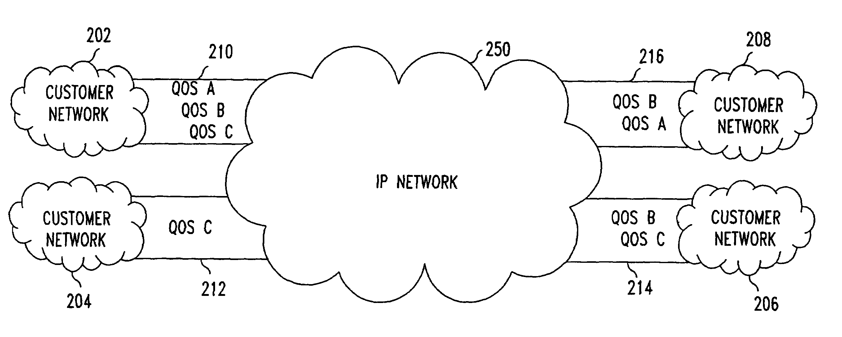
[0038]FIG. 3 shows a diagram illustrating a VPN having customer managed hoses. Each of the customer networks 202–208 may independently define the hose profile for its respective hose 210–216. For example, the customer network 202 has a hose profile that has requirements for QOS A, QOS B and QOS C data packets while the hose profile for the hose 21...

case 4

[0040]In case 4, the VPN service provider establishes various VPNs corresponding to the QOS levels required and the customer networks 202–208 mark each of the data packets corresponding to the QOS level. In this case, the VPN service provider honors the markings of the data packets until the hose profile is reached. For example, if the customer network 202 marks a data packet to be QOS A, the VPN service provider transmits the data packet in the QOS A VPN until the QOS A hose profile is reached. QOS A marked data packets that exceed the hose profile may be given lower priority or best effort performance depending on network conditions. In some situations, the hose profile may specify burst traffic conditions where for a prespecified amount of time, the bandwidth may exceed a base level by some predetermined amount. In this situation, QOS level markings of data packets are ignored only when the burst condition parameters of the hose profile are exceeded. Thus, the VPN service provide...


PUM


Abstract

The invention provides apparatus and methods for a Virtual Private Network (VPN) in a network that offers a simple user interface for efficient utilization of network resources. The VPN is defined for a specified set of endpoints each of which is associated with a single “hose.” A hose provides access to the VPN through an access point which may be a node of the network, for example. The hose is a single interface to the VPN for communication to all other endpoints of the VPN. The VPN achieves network resource allocation efficiency by exploiting resource sharing possibilities via multiplexing routing paths between endpoints and dynamic resource allocation techniques that permit real time resource allocation resizing. When a VPN is established with a VPN service provider, the routing paths between the endpoints of the VPN is optimized for multiplexing opportunities so that resource allocations between nodes along routing paths within the IP network is reduced to a minimum.

Description

[0001]This non-provisional application claims the benefit of U.S. application Ser. No. 09 / 425,565, entitled “VIRTUAL PRIVATE NETWORK” filed on Oct. 19, 1999, which claims the benefit of U.S. Provisional Application No. 60 / 113,497, entitled “PERFORMANCE ORIENTED SERVICE INTERFACE FOR VIRTUAL PRIVATE NETWORKS” filed on Dec. 22, 1998 and U.S. Provisional Application No. 60 / 104,756, entitled “VIRTUAL PRIVATE NETWORK” filed on Oct. 19, 1998. The Applicants of the provisional applications are Nicholas G. Duffield, Pawan Goyal, Albert Gorder Greenberg, Partho Pratim Mishra, Kadangode K. Ramakrishnan, and Jacobus E. van der Merwe. The above provisional applications and “A FLEXIBLE MODEL FOR RESOURCE MANAGEMENT IN VIRTUAL PRIVATE NETWORKS” by Duffield, Goyal, Greenberg, Mishra, Ramakrishnan and van der Merwe are hereby incorporated by reference including all references cited therein.BACKGROUND OF THE INVENTION[0002]1. Field of Invention[0003]The present invention relates to methods and appar...

Claims


Application Information

Patent Timeline
Patent Type & Authority Patents(United States)
IPC IPC(8): H04J3/16H04J3/22
CPCH04L12/4641H04L45/48H04L45/28H04L45/00H04L45/76H04L45/80
Inventor DUFFIELD, NICHOLAS G.GREENBERG, ALBERT G.GOYAL, PAWANMISHRA, PARTHO P.RAMAKRISHNAN, KADANGODE K.VAN DER MERWE, JACOBUS FRASMUS
Owner AMERICAN TELEPHONE & TELEGRAPH CO
Why Eureka
Try Eureka