Configuration of a two-track tractor

a two-track tractor and rear wheel technology, which is applied in the direction of tractor, non-deflectable wheel steering, transportation and packaging, etc., can solve the problems of affecting the mobility affecting the stability of the conventional tractor, and requiring significant weight to be carried on the front wheel mechanism. , to achieve the effect of minimizing the wear of the rubber tread

Active Publication Date: 2013-08-01
CLAAS INDTECHN
View PDF7 Cites 25 Cited by
  • Summary
  • Abstract
  • Description
  • Claims
  • Application Information

AI Technical Summary

Benefits of technology

[0028]Preferably, the front axle suspension comprises an active suspension. In another embodiment, the invention provides an agricultural tractor with a pair of track assemblies including rubber treads with track bars, the track assemblies interconnected by respective front and rear axles extending substantially perpendicular to a direction of travel, a front wheel assembly and a controller or a control system that automatically controls a load imposed on the front wheel assembly i...

Problems solved by technology

In order to steer, however, a significant percentage of the total weight had to be carried on the front wheel mechanism.
This caused the tractor to be extra heavy.
Partial sinking of the front wheel mechanism compromised the conventional tractor's mobility in soft terrain.
Steel tracks with sharp grouser tips have a disadvantage of not being able to travel on paved roads because they tend to damage the road's surface and because of slow travel speeds.
With the advent of paved roads and farmers' fields becoming farther apart, the use of steel tracks came into disfavor.
The dynamics of the two-track configuration include the following: the standard two-track configuration has a steady state harsh ride during road travel because the amount of weight on the track assembly's front spindle is excessive during road travel and because the rear of the tractor has no suspension.
This excessive amount of weight up front also causes rapid wear-out of the rubber belts.
Slip causes wear on the tread bar tips and the rate of wear is proportional to the contact force between the tip and the ground.
This excessive load causes excessive compression in the tread bars below the front idler's centerline 14A.
This compression, in turn, causes the initial contact point of the tread bars to happen several centimeters forward of th...

Method used


Image

  • Configuration of a two-track tractor
  • Configuration of a two-track tractor
  • Configuration of a two-track tractor

Examples


Embodiment Construction

[0050]The following is a detailed description of example embodiments of the invention depicted in the accompanying drawings. The example embodiments are presented in such detail as to clearly communicate the invention and are designed to make such embodiments obvious to a person of ordinary skill in the art. However, the amount of detail offered is not intended to limit the anticipated variations of embodiments; on the contrary, the intention is to cover all modifications, equivalents, and alternatives falling within the spirit and scope of the present invention, as defined by the appended claims.

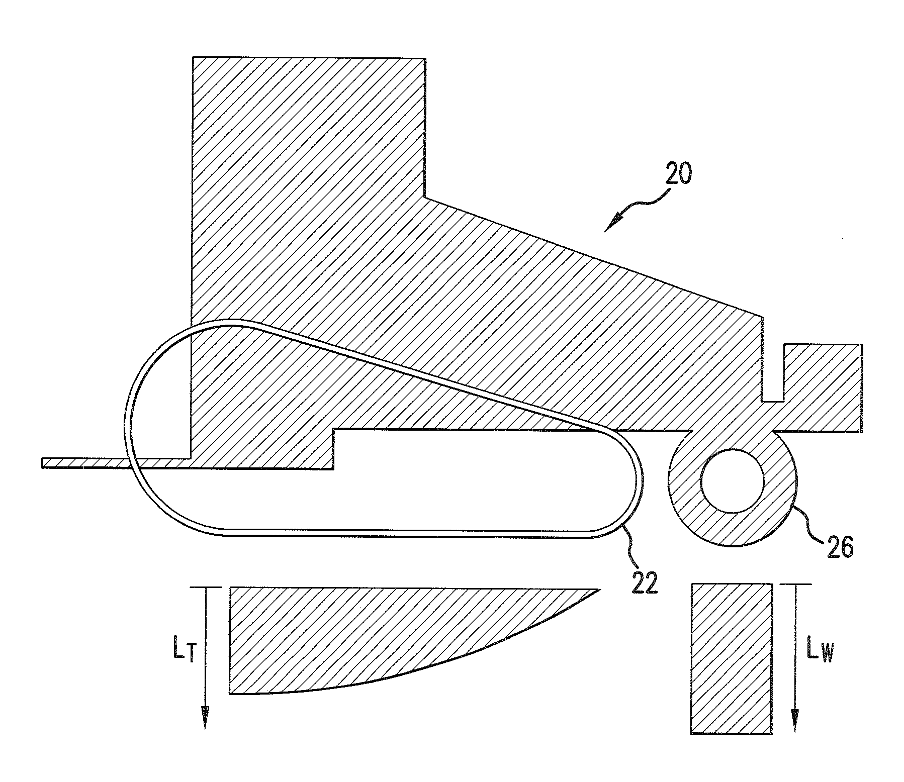
[0051]The present invention, in an embodiment, provides apparatus for a tractor having two rubber track assemblies and a wheel assembly in front of the track assemblies that automatically controls an amount of weight that is imposed on the wheel assembly, for example, to limit or eliminate slip and thereby an amount of wear on tread bars of the track assemblies.

[0052]As described above, som...


PUM


Abstract

A tractor configuration includes a mainframe structure, a control station having a means of controlling the tractor, an undercarriage system having one left side and one right side track assembly, a wheel mechanism containing one or more wheels located forward of the track assemblies, a power train for forcing both track assemblies to travel at the same or different speeds, a controller responsible for exerting force to transfer vertical load back and forth between the front portion of the track assemblies and the wheel mechanism and controlling the amount of weight carried by the wheel mechanism. The controller causes or allows the wheel or wheels of the wheel mechanism to follow the tractor's curved path caused by track speed difference.

Description

CROSS-REFERENCE TO RELATED APPLICATION[0001]This application claims priority from U.S. Provisional Patent Application 60 / 590,990 filed Jan. 26, 2012.BACKGROUND OF THE INVENTION[0002]The present invention relates generally to an apparatus for a tractor having two tracks. More specifically, the apparatus is an improved configuration for a tractor having two track assemblies and a wheel assembly in front of the track assemblies, which wheel assembly is automatically controlled to adjust an amount of weight on the wheel assembly, for example, to limit or eliminate slip and thereby an amount of wear on tread bars of the track assemblies. Such apparatus thereby solves multiple problems encountered with current two-track tractors using two rubber belt tracks.[0003]Both a two-track tractor configuration and a half-track tractor configuration are well known. The earliest large farm tractors often were half-track configurations having a combination of steel tracks and wheels. For traction, tr...

Claims


Application Information

Patent Timeline
IPC IPC(8): B60G17/016B62D11/10B62D49/06
CPCB62D55/116B60G17/016B62D49/0635B62D11/10B62D49/00B62D11/24B62D37/04B62D49/0621B62D29/008B62D55/02B62D49/06
Inventor JANZEN, DAVID C.SATZLER, RONALD L.
Owner CLAAS INDTECHN
Why Eureka
Try Eureka