
Washing machine and method of controlling washing machine

a technology of washing machine and pulsator, which is applied in the direction of washing machine with receptacle, other washing machines, textiles and paper, etc., can solve the problems of inability to accurately measure the load of laundry, inability to smoothly realize the rotation of the pulsator, and inability to accurately detect the degree of unbalance of laundry, etc., to achieve optimal washing performance, reduce water and electric consumption of washing machines, and reduce the effect of wear of laundry

Active Publication Date: 2012-03-15
LG ELECTRONICS INC
View PDF4 Cites 35 Cited by
  • Summary
  • Abstract
  • Description
  • Claims
  • Application Information

AI Technical Summary

Benefits of technology

[0017]An advantage of the invention is to provide a method of controlling a washing machine that can provide optimal washing performance by applying different washing patterns in accordance with a determined result of whether the laundry loaded in the drum is dry laundry (e.g., little to no water content) or wet laundry. With knowledge of this information, the water and electric consumption of the washing machine can be reduced and the wear of the laundry can be reduced as compared with the prior art control method where the washing pattern is determined in accordance with the wet laundry load detected in a state where wet laundry is loaded.
[0018]Another advantage of the invention is to provide a washing machine that can stably maintain the coupling of the supporting member and the weight detecting sensor using adaptor having screw threads having different thread directions.
[0019]Additional features and advantages of the invention will be set forth in the description that follows, and in part will be apparent from the description, or may be learned by practice of the invention. The advantages of the invention will be realized and attained by the structure particularly pointed out in the written description and claims hereof as well as the appended drawings.
[0020]To achieve these and other advantages and in accordance with the purpose of the invention, as embodied and broadly described, a method of controlling a washing machine including a casing, a tub suspended in the casing, a drum rotatably provided in the tub, and a pulsator rotatably provided in the drum may include: detecting a first laundry load based on a rotational property of the pulsator; detecting a second laundry load based on a property that varies in accordance with a vertical load applied by the tub; determining if laundry loaded in the drum is in a dry state or a wet state by comparing a first laundry load with a second laundry load.
[0021]In yet another aspect of the invention, a washing machine includes: a casing; a tub disposed in a casing; a drum which is rotatably provided inside the tub and in which laundry is loaded; at least one supporting member suspending the tub in the casing and comprising upper and lower bars; a weight detecting sensor provided between the upper and lower bars and configured to detect a weight of the laundry; and at least one adaptor, coupling one of the upper and lower bars to the weight detecting sensor, wherein the adaptor includes: a sensor coupling portion to which the weight detecting sensor is coupled; and a supporting member coupling portion to which one of the upper and lower bars is coupled, wherein the sensor coupling portion and the supporting member coupling portion are formed with respective screw threads having different thread directions.

Problems solved by technology

However, because the above-described method is an indirect method in which the rotational property of the pulsator is observed and the laundry load is assumed based on the observed rotational property, it is impossible to accurately measure the laundry load.
Likewise, the accuracy of detection of a degree of unbalance of the laundry is deteriorated.
For example, when the laundry gets tangled in the drum, the rotation of the pulsator cannot be smoothly realized even when a small amount of the laundry is loaded in the tub.
Therefore, it may be erroneously detected that a large amount of the laundry is loaded.

Method used


Image

  • Washing machine and method of controlling washing machine
  • Washing machine and method of controlling washing machine
  • Washing machine and method of controlling washing machine

Examples


Embodiment Construction

[0059]Reference will now be made in detail to embodiments of the invention, examples of which are illustrated in the accompanying drawings. This invention may, however, be embodied in many different forms and should not be construed as limited to the exemplary embodiments set forth herein. Rather, these exemplary embodiments are provided so that this disclosure is thorough, and will fully convey the scope of the invention to those skilled in the art. Wherever possible, the same reference numbers will be used throughout the drawings to refer to the same or like parts.

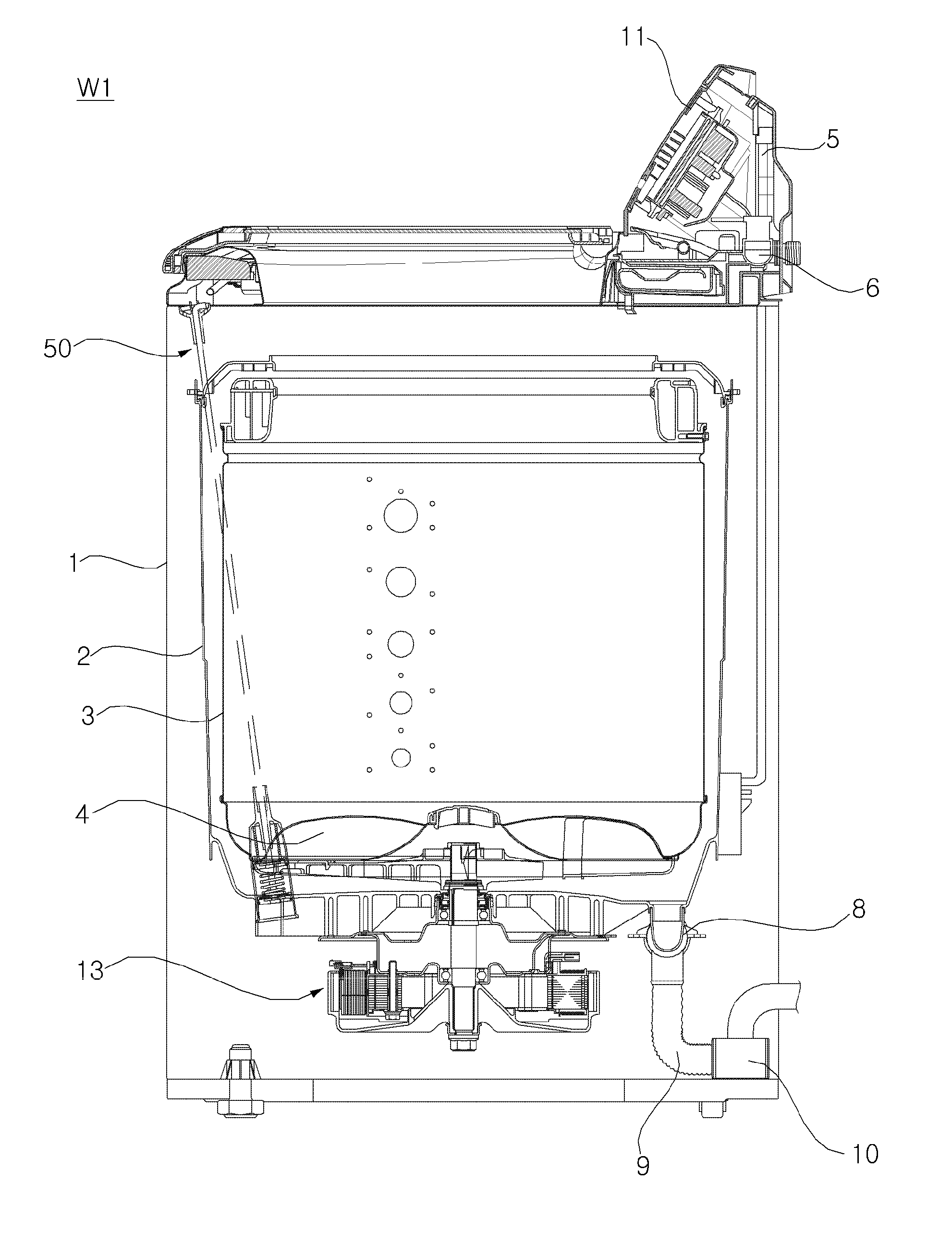
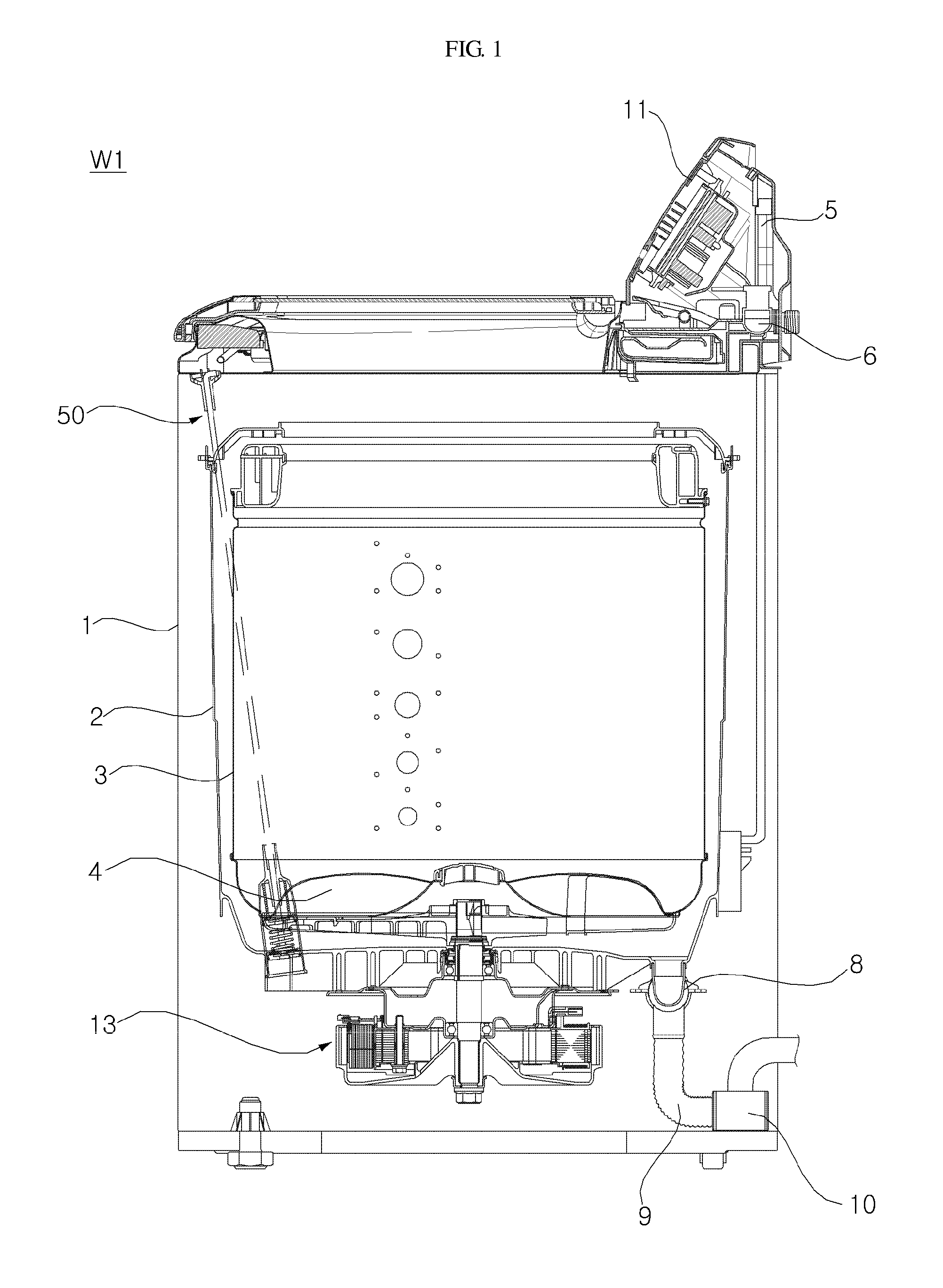
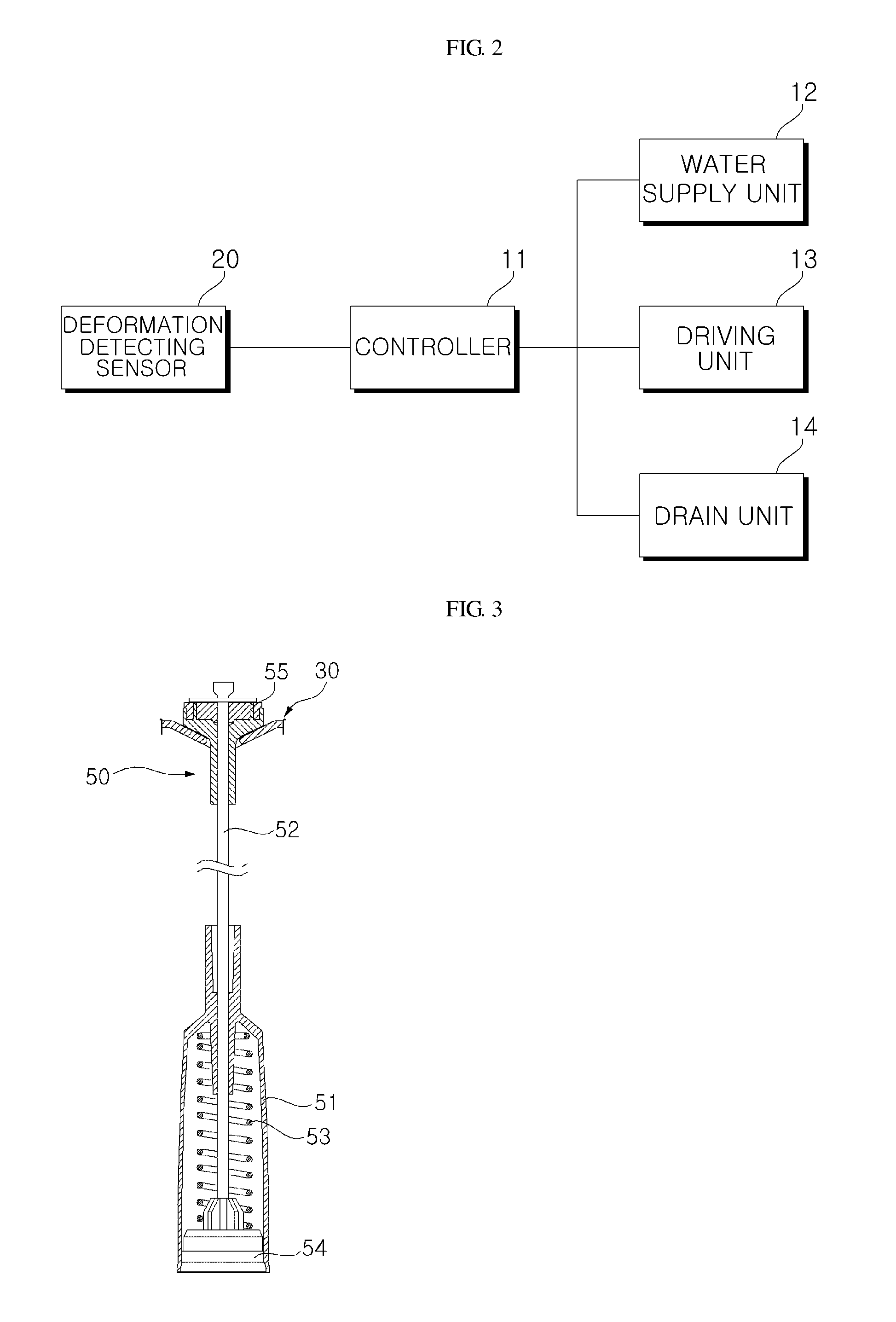
[0060]FIG. 1 is a schematic cross-sectional view of a washing machine according to an embodiment of the invention. FIG. 2 is a block diagram illustrating a control relationship between parts of a washing machine according to an embodiment of the invention.

[0061]Referring to FIGS. 1 and 2, a washing machine W1 according to an embodiment of the invention includes a casing 1 defining the appearance of the washing machine W1...


PUM


Abstract

A method of controlling a washing machine is provided. A first laundry load is first detected based on a rotational property of a pulsator. A second laundry load is detected based on a property that varies in accordance with a vertical load applied from a tub. Finally, it is determined if laundry loaded in the drum is in a dry state or a wet state by comparing the first laundry load with the second laundry load.

Description

CROSS-REFERENCE TO RELATED APPLICATIONS[0001]This application claims priority from Korean Patent Application No. 10-2010-0090155 filed in Korea on Sep. 14, 2010, No. 10-2010-0090156 filed in Korea on Sep. 14, 2010, No. 10-2010-0090764 filed in Korea on Sep. 15, 2010, No. 10-2010-0094613 filed in Korea on Sep. 29, 2010, No. 10-2010-0112254 filed in Korea on Nov. 11, 2010, No. 10-2011-0019134 filed in Korea on Mar. 3, 2011, No. 10-2011-0019135 filed in Korea on Mar. 3, 2011, the contents of which are incorporated herein by reference for all purposes as if fully set forth herein.BACKGROUND[0002]1. Field[0003]Exemplary embodiments of the invention relate to a washing machine and a method of controlling the washing machine.[0004]2. Background[0005]In general, a washing machine is designed to wash the laundry using emulsification of a detergent, a water stream action generated by the rotation of washing blades or washing tub, and an impact action applied by the washing blades. The washing...

Claims


Application Information

Patent Timeline
IPC IPC(8): D06F33/00D06F37/26D06L1/16D06F21/00
CPCD06F21/08D06F23/04D06F39/003D06F37/24D06F37/203D06F34/18D06F2105/58D06F2105/02D06F2103/04D06F2105/48D06F2105/60D06F33/32D06F2103/18D06F2103/38D06F2103/26D06F33/40
Inventor KIM, YOUNGJONGMOON, TAECHUL
Owner LG ELECTRONICS INC
Learn More