Breakaway conveyor discharge

a conveyor and breakaway technology, applied in the direction of conveyor parts, roller-ways, transportation and packaging, etc., can solve the problems of substantial gap, jamming of packages, and conveyors may also be damaged

Inactive Publication Date: 2007-02-01
DEMATIC
View PDF5 Cites 39 Cited by
  • Summary
  • Abstract
  • Description
  • Claims
  • Application Information

AI Technical Summary

Benefits of technology

[0006] The present invention provides a breakaway conveyor discharge member which mitigates the above-discussed difficulties.
[0007] According to one aspect of the present invention, a conveyor system is provided. The conveyor system includes first and second conveying surfaces conveying objects in a longitudinal direction and defining a gap at a transition between the conveying surfaces with a conveyor discharge member at the gap. The conveyor discharge includes a plate defining a generally planar surface between the conveying surfaces. The conveyor discharge member is movable in response to a particular longitudinal force to reduce jam locations between the conveyor discharge member and the conveying surfaces.
[0010] In another form of the present invention, a method for reducing jams of an object between first and a second conveying surfaces is provided. The method includes receiving a conveyor discharge member between the first and second conveying surfaces providing a planar surface between the first conveying surface and the second conveying surface and dislodging the conveyor discharge member from between the first and second conveying surfaces in response to a particular longitudinal force applied in an area of the first conveying surface and the conveyor discharge member.
[0011] Therefore, the present invention provides a conveyor system including a conveyor discharge member between first and second conveying surfaces. The conveyor system includes a conveyor discharge member received by a frame, which is connected between the conveying surfaces. The discharge conveyor member provides a generally planar surface between the first and second conveying surfaces and supports a substantial vertical load, such as the weight of a person. When a conveyed object creates a sufficiently strong longitudinal force upon the conveyor discharge member, it is assumed to be a package jam, and the conveyor discharge member dislodges from a set of brackets mounted on the frame to reduce the likelihood of damage. When the conveyor discharge member dislodges from the brackets, the first conveying surface may be halted to prevent any damage to the conveyed objects or conveying surfaces.

Problems solved by technology

These large sprockets or wheel guides often impart a large radius of curvature to the slat web thereby forming rounded ends and producing a substantial gap between a discharge conveying surface and the adjacent charge conveying surface.
However, even with transition plates placed between tandem conveying surfaces, jamming of packages may occur in the gap area between the transition plate and the discharge conveying surface.
Jams may result from objects protruding from conveyed packages which may catch in this gap area.
Thus, when jams occur at such a high rate of speed, conveyed objects may be damaged, subsequent objects may slam into jammed objects, and the conveyors may also be damaged.

Method used


Image

  • Breakaway conveyor discharge
  • Breakaway conveyor discharge
  • Breakaway conveyor discharge

Examples


Embodiment Construction

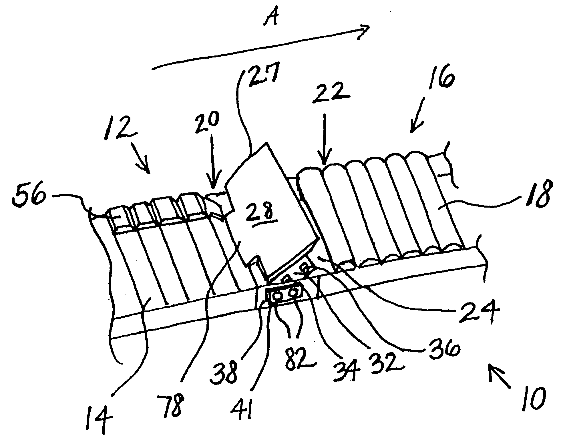
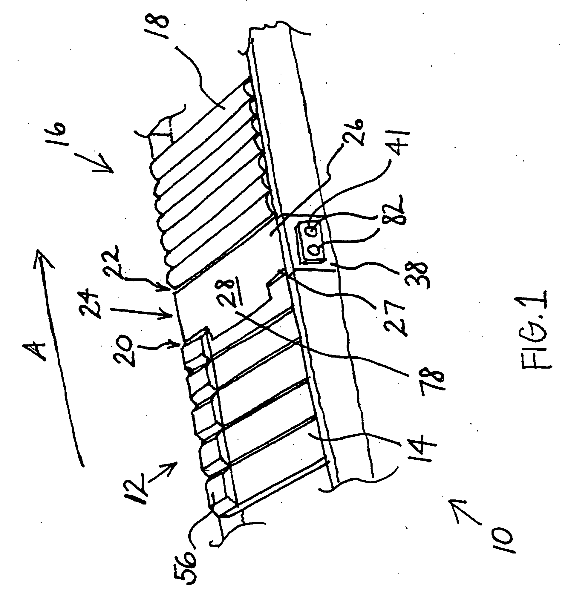
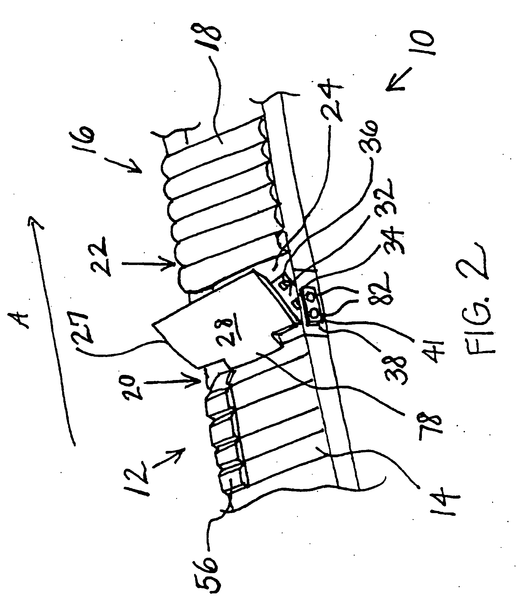
[0024] Referring now to the figures, a conveyor system 10 includes a first conveyor system 12 with a first slat conveying surface 14 and a second conveyor system 16 with a second conveying surface 18, as best illustrated in FIGS. 1 and 2. First conveying surface 14 includes a discharge end 20 and second conveying surfaces includes a charge end 22. Discharge end 20 and charge end 22 may both have a large radius of curvature due to sprockets or pulleys at each end with a large radius. When adjacent discharge end 20 and charge end 22 are placed in tandem or in series, the ends may form a non-planar gap 24 between conveying surfaces 14, 18. A conveyor discharge member 26 is placed in gap 24 to provide a generally planar surface 28 for smooth transitioning of conveyed objects in a longitudinal direction, A, between conveying surfaces 14, 18, as best illustrated in FIG. 1. Conveyor discharge member 26, which may also be referred to as a breakaway conveyor discharge member, is able to with...


PUM


Abstract

A breakaway conveyor discharge member received between first and second conveying surfaces is provided. The conveyor discharge member is received by a bracket mounted on a frame connected between the first and second conveying surfaces. The conveyor discharge member includes a generally planar surface between the first and second conveying surfaces. The conveyor discharge member can withstand a vertical load substantially greater than a particular longitudinal load on the planar surface. Under normal operating conditions, the conveyor discharge member conveys the object from the first conveyor surface onto the intake conveying surface. Under jam conditions, when the substantially longitudinal load is great enough, the conveyor discharge member dislodges from the brackets to protect the first and second conveying surfaces by eliminating the jam point.

Description

CROSS REFERENCE TO RELATED APPLICATION [0001] This application claims priority from U.S. provisional patent application Ser. No. 60 / 703,269, filed on Jul. 28, 2005, the disclosure of which is hereby incorporated herein by reference in its entirety.BACKGROUND OF THE PRESENT INVENTION [0002] The present invention pertains to a conveyor system and more particularly to a conveyor discharge, or transition section, received between a discharge conveying surface and an intake conveying surface. [0003] Conventional slat conveyor systems often consist of conveyor beds with large radius sprockets or wheel guides at the charge end and the discharge end. These large sprockets or wheel guides often impart a large radius of curvature to the slat web thereby forming rounded ends and producing a substantial gap between a discharge conveying surface and the adjacent charge conveying surface. Accordingly, a transition surface may be required to compensate for the large radius of curvature of the roun...

Claims


Application Information

Patent Timeline
Patent Type & Authority Applications(United States)
IPC IPC(8): B65G47/46
CPCB65G47/66
Inventor SCHIESSER, RICARDO N.
Owner DEMATIC
Why Eureka
Try Eureka