Aircraft braking method and apparatus

a technology for aircraft and braking, applied in the direction of braking system, brake action initiation, position/direction control, etc., can solve the problems of aircraft wheel proneness, aircraft lock-up completely, aircraft's ability to decelerate by applying brakes, etc., to achieve the effect of reducing one or improving braking

Inactive Publication Date: 2007-10-23
AIRBUS OPERATIONS LTD
View PDF13 Cites 36 Cited by
  • Summary
  • Abstract
  • Description
  • Claims
  • Application Information

AI Technical Summary

Benefits of technology

[0008]It is an object of the present invention to provide a method of braking and a braking apparatus that mitigates one or more of the above-mentioned disadvantages and / or to provide an improved method of braking and an improved braking apparatus.

Problems solved by technology

The wheels of the aircraft are prone, when subjected to a sufficient braking torque, to skidding and may, in severe cases, lock-up completely.
When the wheels are skidding the ability of the aircraft to decelerate by application of the brakes is impaired.

Method used


Image

  • Aircraft braking method and apparatus
  • Aircraft braking method and apparatus
  • Aircraft braking method and apparatus

Examples


Embodiment Construction

[0059]The embodiment of the present invention relates to a braking control system for controlling the braking of a wheel of an aircraft landing gear assembly during landing of the aircraft.

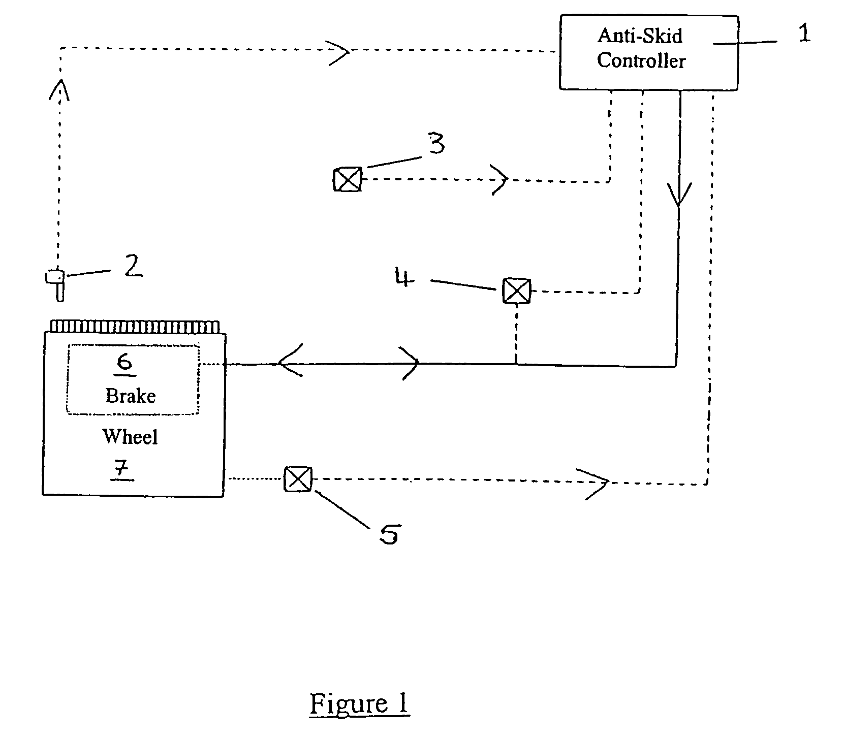
[0060]FIG. 1 shows a schematic diagram illustrating the operation of the braking control system of the present invention. The system comprises an anti-skid controller 1 which is connected to a wheel speed transducer 2, a vehicle velocity transducer 3, a brake actuation transducer 4 and a vertical load transducer 5. The anti-skid controller 1 is also connected to a brake 6, which is able to effect a braking action on the wheel 7.

[0061]Vertical loads between the ground and the wheel are ascertained by means of strain gauges on the landing gear, an electronic signal representative of the vertical load so ascertained being sent from the vertical load transducer 5 to the anti-skid controller 1. Strain gauges, such as piezo-electric strain gauges, may be used to measure individual, paired or grouped whe...


PUM


Abstract

An aircraft is decelerated by applying a braking force to a wheel of the aircraft as it moves along the ground. An anti skid controller calculates the braking force to be applied by taking into account data relating to the vertical load transmitted between the ground and the wheel and data relating to the slip between the ground and the wheel. Predictions (box 13b) made regarding how the vertical load will change and data (box 13a) concerning the relationship between slip and the ground to wheel friction coefficient are both taken into account when calculating the braking force to be applied. Skids may thereby be predicted in advance and may be reduced or even avoided.

Description

BACKGROUND OF THE INVENTION [0001]The present invention relates to decelerating an aircraft and, in particular, to a method of applying a braking force to the wheel of an aircraft and to a braking apparatus for performing such a method.[0002]After having touched-down on landing, an aircraft is caused to decelerate in various ways, one example of which being by means of application of a braking torque to the wheels of the aircraft. It is desirable to decelerate the aircraft in an efficient and controlled manner. Thus, it is desirable to maximise the pilots demand for deceleration of the aircraft by means of the braking torque applied to the wheels. The wheels of the aircraft are prone, when subjected to a sufficient braking torque, to skidding and may, in severe cases, lock-up completely. It will be appreciated that there is generally some slip between the wheels and the ground when the aircraft is moving, but that above a given amount of slip the wheels can be considered as skidding...

Claims


Application Information

Patent Timeline
Patent Type & Authority Patents(United States)
IPC IPC(8): B60T8/00B60T8/32B60T8/17
CPCB60T8/325B60T8/1703
Inventor DARKE, JASON WILLIAM
Owner AIRBUS OPERATIONS LTD
Why Eureka
Try Eureka