
Establishing connection across a connection-oriented first telecommunications network in response to a connection request from a second telecommunications network

a telecommunications network and connection technology, applied in the field of communication across a telecommunications network, can solve the problems of difficult integration of gmpls into optical networks, information may be considered to be commercially sensitive, and the public availability of topological information may be undesirable, so as to achieve the effect of reducing one or more of the problems

Inactive Publication Date: 2010-11-09
TELEFON AB LM ERICSSON (PUBL)
View PDF39 Cites 4 Cited by
  • Summary
  • Abstract
  • Description
  • Claims
  • Application Information

AI Technical Summary

Benefits of technology

[0008]It is therefore an object of the present invention to provide a method of communicating across a telecommunications network which allows a given protocol, for example a protocol used in an MPLS environment, to be used in combination with other networks, for example optical networks, and which mitigates one or more of the problems associated with the above-mentioned proposals. The present invention also seeks to provide suitable means or apparatus for performing such a method or aspects of such a method.
[0019]Advantageously the communications network further comprises a further edge network element for connecting the communications network to a third communications network, the third network comprising a plurality of network elements each of which is capable of making connections or routing data across the third network in accordance with a connection request received by the element, the network management system being configured to cause the further edge network element to send a connection request according to the predetermined protocol to the third network thereby enabling connection of the second and third networks via the communications network. Such a network is advantageous where the third network requires a connection request according to the predetermined protocol to be received before a connection can be made. Since the network management system causes the further edge network to send the connection request this eliminates the need for the further edge network element to be able to itself generate the connection request.

Problems solved by technology

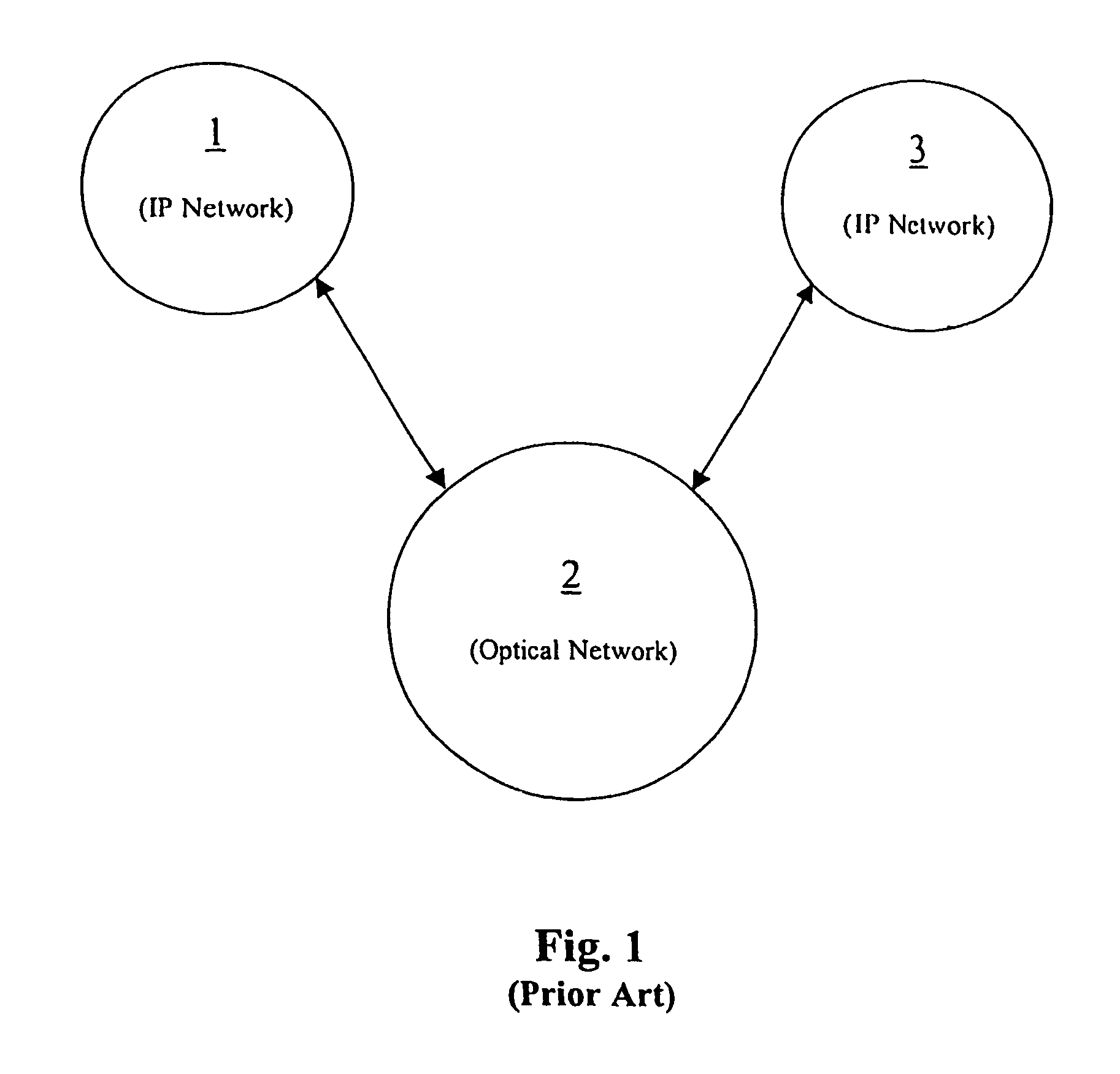
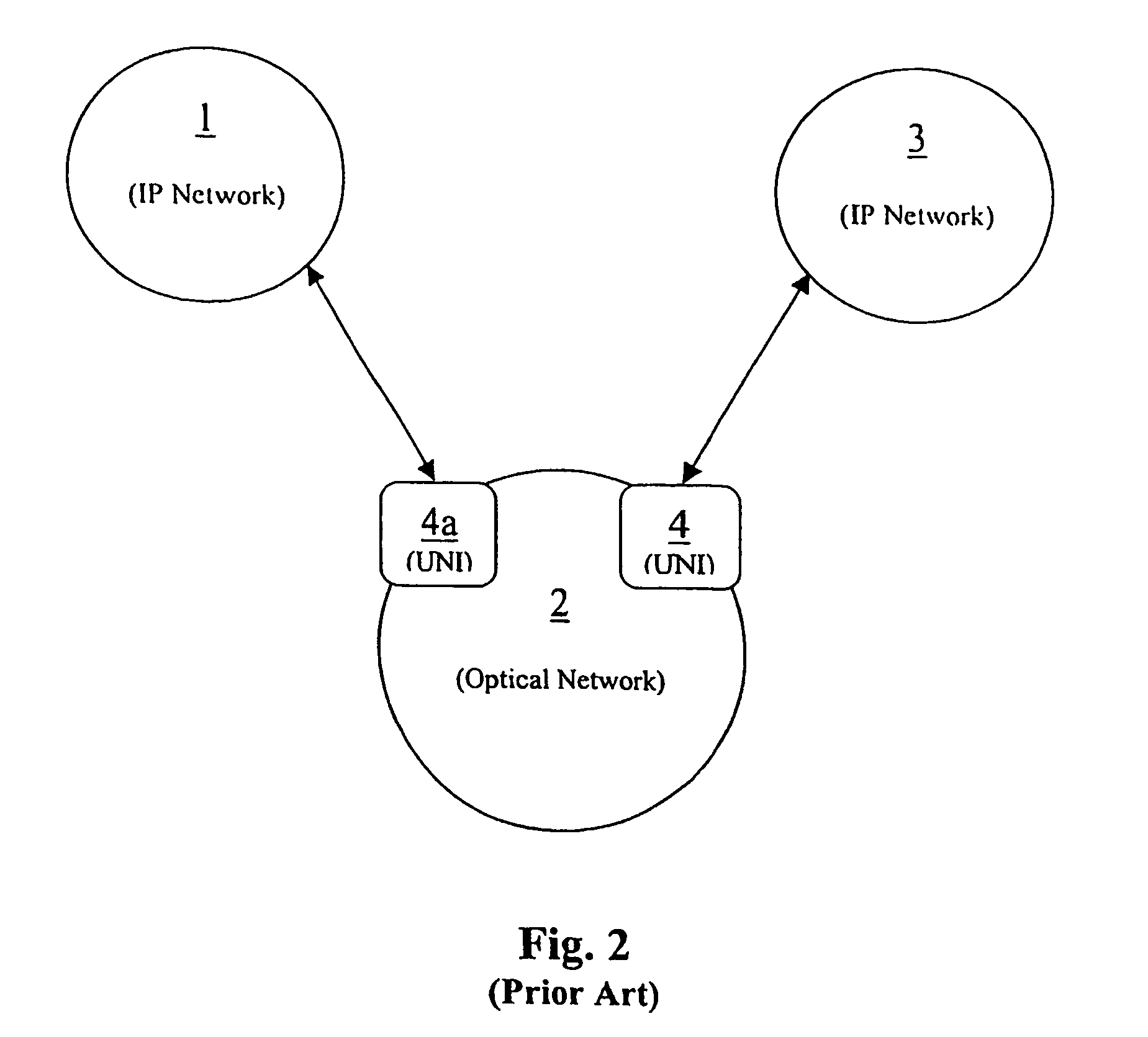
However, incorporating GMPLS into an optical network is not straightforward.
If the optical network 2 is privately owned, making such topological information publicly available may however be undesirable.
For example, such information may be considered to be commercially sensitive and it may be desired to keep such information confidential.
Both of the proposals described above suffer from a significant disadvantage.
Whilst such requirements can be met when installing new optical networks, many existing optical network elements are not able to perform at the required level.
Replacing such existing optical networks (often referred to as legacy networks) would be costly and is therefore undesirable.

Method used


Image

  • Establishing connection across a connection-oriented first telecommunications network in response to a connection request from a second telecommunications network
  • Establishing connection across a connection-oriented first telecommunications network in response to a connection request from a second telecommunications network
  • Establishing connection across a connection-oriented first telecommunications network in response to a connection request from a second telecommunications network

Examples


first embodiment

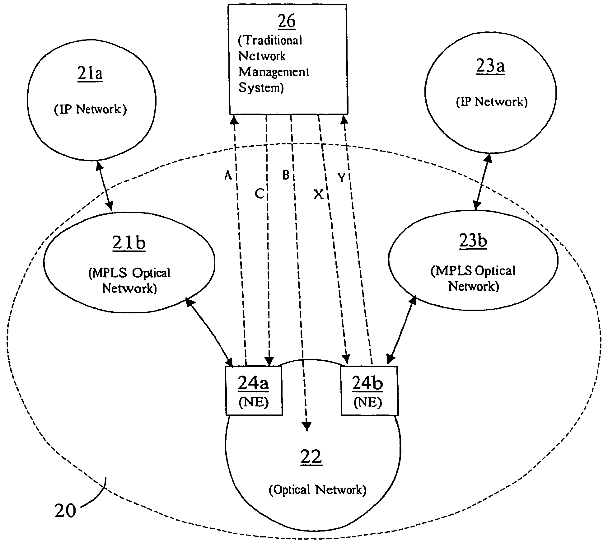
[0030]A telecommunications network according to the invention is shown in FIG. 3. With reference to FIG. 3 the network includes a first MPLS enabled IP network 11 connectable to a second MPLS enabled IP network 13 via a legacy optical network 12. The legacy optical network 12 includes a plurality of internal network elements 15 (only one of which is shown in FIG. 3 for the sake of clarity) and a plurality of edge network elements 14a, 14b (only two of which are shown). The legacy optical network 12 is also connected to a traditional network management system 16.

[0031]At the interface between the first IP network 11 and the optical network 12, signals may be received and sent by an edge network element 14a of the optical network 12. Similarly, at the interface between the second IP network 13 and the optical network 12, signals may be received and sent by an edge network element 14b of the optical network 12. Network access and connection requests may be made through the edge network...

second embodiment

[0047]Also, two IP networks could be connected via an optical network, such that a first IP network is connected to a single legacy network, which is connected to a single MPLS optical network, which is connected to a second IP network. In such a case, the receipt from the first network of a UNI request requesting connection to the second IP network would be handled in a similar manner to that described with reference to the The UNI request would be passed from an ingress legacy network element to the network management system of the legacy network, which would set a connection, send a UNI request via an egress legacy network element to the MPLS optical network, receive an appropriate response via the egress legacy network element from the MPLS optical network, and then cause the ingress legacy network element to send an appropriate response to the requesting IP network, data thereafter being transmitted from the first IP network across the optical network and to the second IP netw...


PUM


Abstract

A first multi protocol label switching (MPLS) enabled Internet Protocol (IP) data network is able to transmit data to a second MPLS enabled IP network via a legacy optical network, which would not otherwise be able to handle the user network interface (UNI) protocols required to be used within an MPLS network environment, by means of configuring the legacy optical network and its traditional network management system (TNMS) so that they simulate or emulate an MPLS enabled optical network. The simulation / emulation of an MPLS network is performed as follows: when a first legacy network element (NE) receives a connection request (a UNI request) from the MPLS network under a UNI protocol, the UNI request is passed to the TNMS, which then sets the required connection across the legacy network via a second edge NE to an NE of the second IP network. Once the connection has been set, the TNMS instructs the edge NE to send a return signal to the requesting network indicating that the connection has been successfully set. Data packets may then be transmitted across the network.

Description

BACKGROUND OF THE INVENTION[0001]The present invention relates to a method of communicating across a telecommunications network and associated apparatus. In particular, the invention relates to a method of communicating across a telecommunications network, to a telecommunications network, to a network management system for setting connections in a network and to a network element of such networks.[0002]Telecommunications networks, particularly optical networks, have in the past routed data across the network by setting routes by means of a manually operated network management system. When changes are required to be made to the route or routes set in the network, response times can be very long in comparison to the rate of transmission of data.[0003]Significant improvements in routing of data have been made in recent years in the context of electrical networks. One such improvement is the ability of network elements of the network to route data packets without reverting to a separate...

Claims


Application Information

Patent Timeline
IPC IPC(8): H04L12/28H04L12/46H04L45/50H04Q11/00
CPCH04L12/46H04L45/04H04L45/502H04Q11/0062H04B10/271H04Q11/0066H04Q11/0071H04Q2011/0077H04Q2011/0088H04Q2213/1301H04Q2213/13204H04Q2213/13348H04Q2213/13349H04Q2213/1338H04Q2213/13389Y10S370/902
Inventor BARKER, ANDREW JAMES
Owner TELEFON AB LM ERICSSON (PUBL)
Learn More