Thermal blanket including a radiation layer

Inactive Publication Date: 2005-09-22
HALE NICHOLAS
View PDF15 Cites 22 Cited by
  • Summary
  • Abstract
  • Description
  • Claims
  • Application Information

AI Technical Summary

Benefits of technology

[0017] In many modern applications, known insulation blankets or panels are impractical or provide reduced performance for many reasons, such as, weight, thickness, or durability of the materials used. The present invention improves on that state of the art by providing a product for providing fire resistance and thermal insulation, consisting of a metallic foil encapsulated non-woven insulation blanket layer consisting essentially of layers of a woven silica-based cloth and a carbon radiation barrier. This new and improved thermal blanket is a flexible composite, removable thermal blanket using a combination of insulation and other materials that cost-effectively provides an optimum combination of thermal resistivity, radiation resistance, user safety and blanket longevity. A key factor in designing an improved thermal blanket is increasing the thermal resistivity of the non-woven carbon radiation barrier layer so that the blanket as a whole may provide even higher temperature resistance. This is accomplished as provided by the present invention by using a composite thermal radiation barrier comprising alternating layers of a carbon cloth insulating layer and a silica-based organic cloth to enhance the temperature management by the insulating layers. Accordingly, this invention provides for a ceramic fiber composite material that overcomes many problems associated with conventional techniques in the art.
[0018] The improved insulation blanket of the present invention has allowed a turbo air inlet of a turbo-charged automobile engine to run approximately

Problems solved by technology

In many modern applications, known insulation blankets or panels are impractical or provide reduc

Method used


Image

  • Thermal blanket including a radiation layer
  • Thermal blanket including a radiation layer
  • Thermal blanket including a radiation layer

Examples


Example

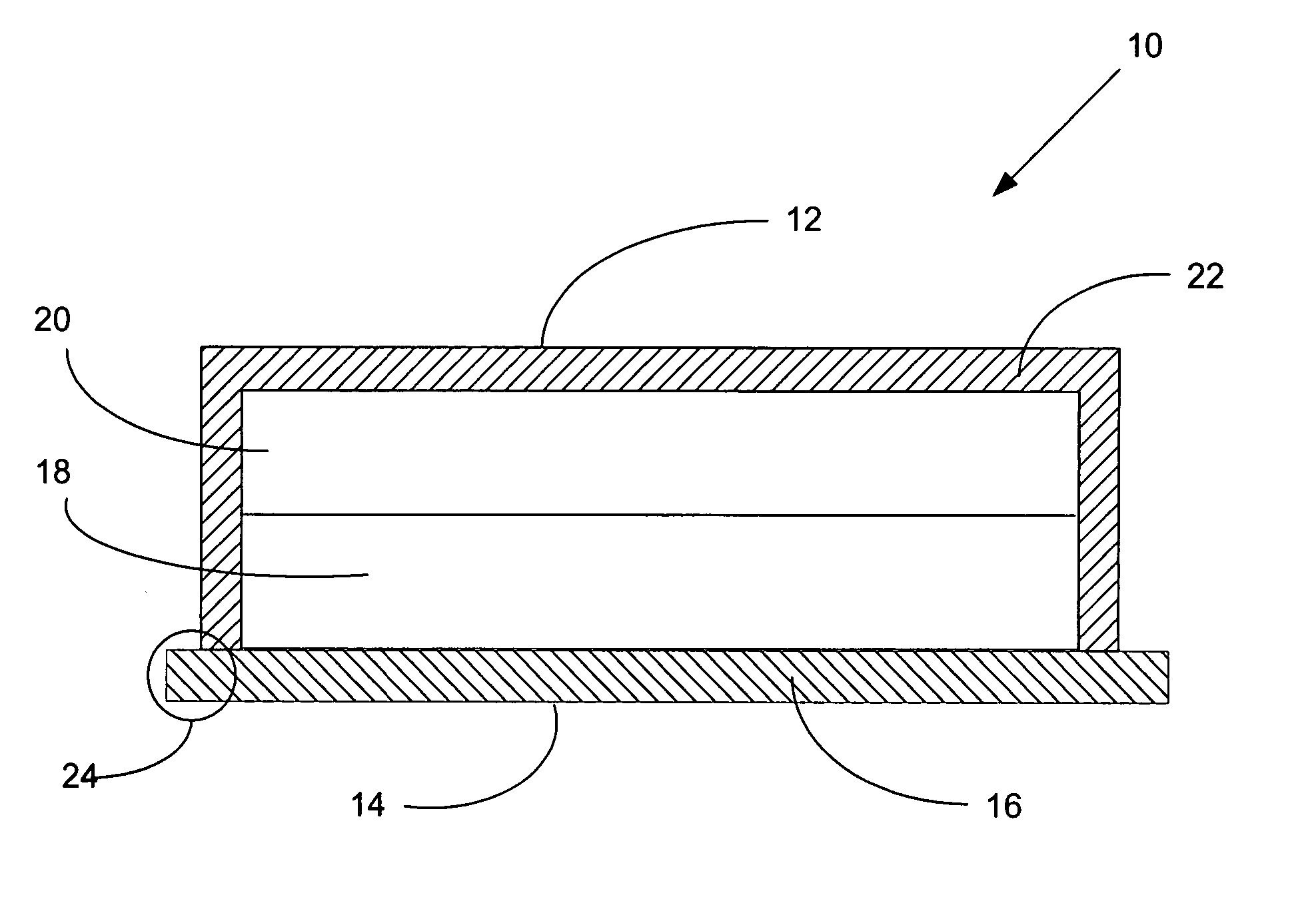
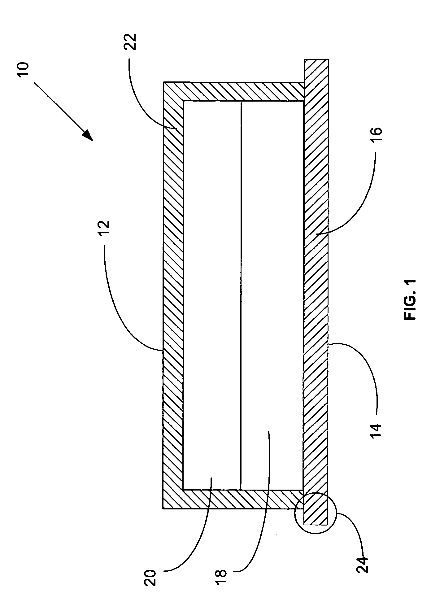
[0026] As seen in FIG. 1, the thermal insulation blanket 10 of the present invention comprises a two-sided blanket 10 having a “bottom side”14 placed adjacent the heat source to be insulated and a “top side”12 adjacent the environment to be thermally protected. FIG. 1 shows an exemplary 4-layer thermal blanket 10 as preferably made of a heat-resistant, flexible metallic woven or knit mesh layer 16 which is finished as a reflective barrier against radiant heat. Next adjacent to metallic layer 16 is a conventional primary insulation layer 18 comprising silica, or silicon dioxide, a compound of two elements in the earth's crust, silicon and oxygen, SiO2,occurring in crystalline, amorphous, and impure forms. Next adjacent to the primary insulation layer 18 is a radiation barrier layer 20 comprising a non-woven carbon cloth layer. Carbon fiber woven and non-woven fabrics are know to be made by entangling short fibers as opposed to weaving long fibers or yarns of carbon. Next adjacent to ...


PUM

PropertyMeasurementUnit
Thicknessaaaaaaaaaa
Weightaaaaaaaaaa
Thermal conductivityaaaaaaaaaa

Abstract

A thermal management system utilizing a composite thermal radiation barrier comprising alternating layers of a carbon cloth insulating layer and a silica-based organic cloth to reduce the temperatures experienced by the insulating layer.

Description

[0001] This application is a divisional of Ser. No. 10 / 238,413, filed Sep. 10, 2202, abandoned, and claims the benefit of U.S. Provisional Application No. 60 / 323,933, filed Sep. 21, 2001.FIELD OF THE INVENTION [0002] The present invention relates to a heat resistant insulation blanket used to control heat energy produced within vehicles, ships, aircraft, and similar machines. More particularly, the present invention provides a thermal insulation blanket comprising a primary insulation layer and a radiation barrier with adjoining insulation layers of a reflective metallic mesh and of silica fabric layer coated with silicone. BACKGROUND OF THE INVENTION [0003] Insulation blankets and panels have been used for many years to control effects of heat generated by engines, exhaust components, furnaces, any auxiliary power unit, fuel-burning heaters, and other combustion equipment intended for in transit use. For example, in aircraft, the combustion, turbine, and tailpipe sections of turbin...

Claims


Application Information

Patent Timeline
IPC IPC(8): B32B5/02B32B5/26B32B9/00B32B15/02B32B17/02B32B27/12F16L59/02
CPCB32B5/02B32B5/26B32B9/00F16L59/029B32B17/02B32B27/12F16L59/021B32B15/02Y10T442/172Y10T442/109Y10T442/259Y10T442/2984Y10T442/2926Y10T442/2607Y10T442/2975Y10T442/20
Inventor GOOLIAK, ROBERT M.
Owner HALE NICHOLAS
Why Eureka
Try Eureka