

Capsule for medical use
a technology for medical use and capsules, applied in the field of capsules for use, can solve problems such as affecting the quality of communication, and achieve the effect of satisfying communication conditions
- Summary
- Abstract
- Description
- Claims
- Application Information
AI Technical Summary
Benefits of technology
Problems solved by technology
Method used
Image

Examples
first embodiment
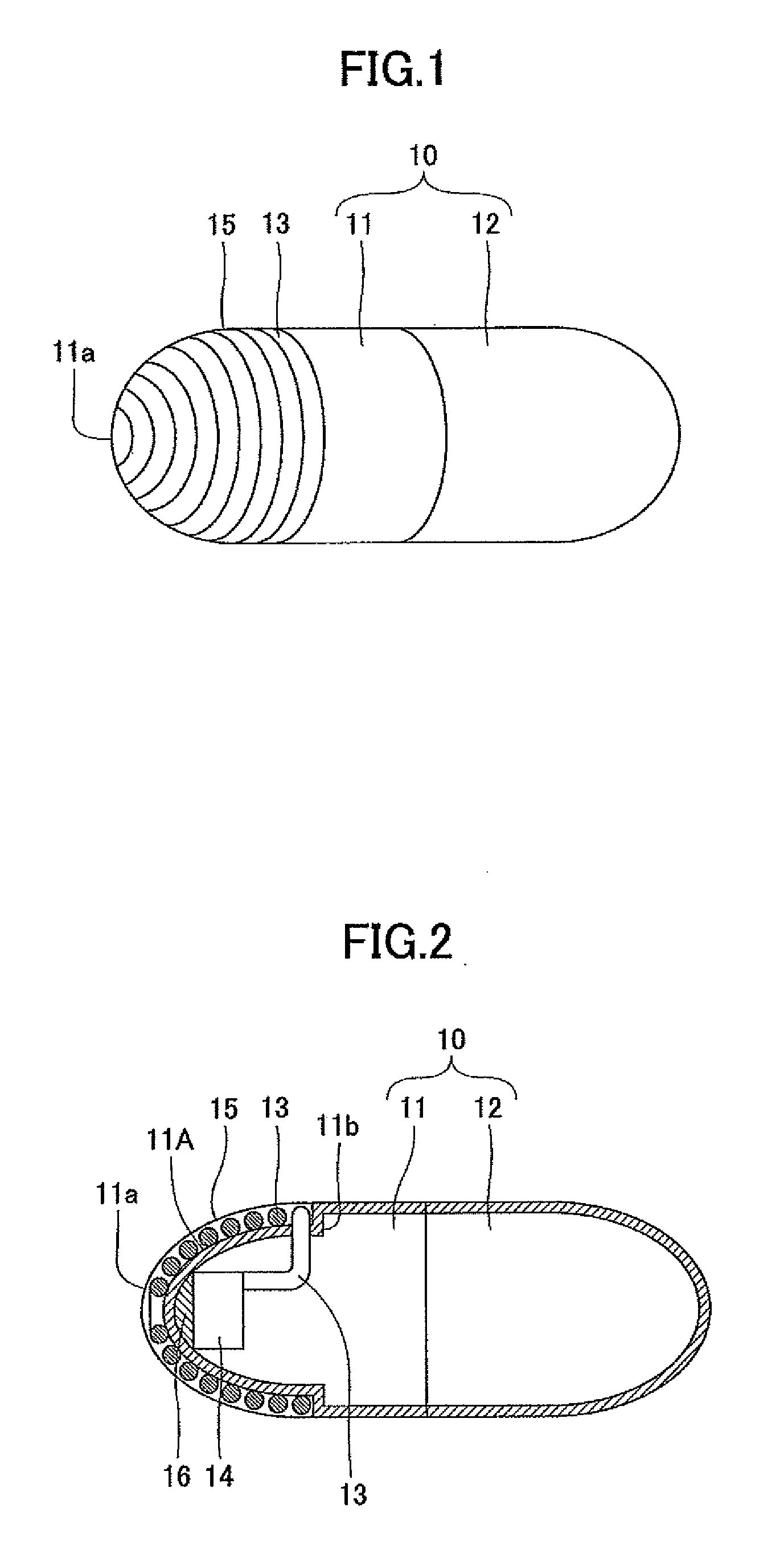
[0023]FIG. 1 is a perspective view of a capsule for use with a medical device according to a first embodiment.
[0024]A capsule 10 is a resin cylinder having ends thereof rounded into a hemispherical shape. The capsule 10 is 10 mm in length and 6 mm in diameter. The resin material constituting the capsule 10 may be an ABS (acrylonitrile butadiene styrene) resin, for example.
[0025]The capsule 10 is assembled by hermitically connecting a pair of capsule parts 11 and 12. An end 11a of the capsule part 11 has an antenna part 13 wrapped around its outer circumferential surface.
[0026]FIG. 2 is a cross-sectional view of the medical device capsule of the first embodiment.
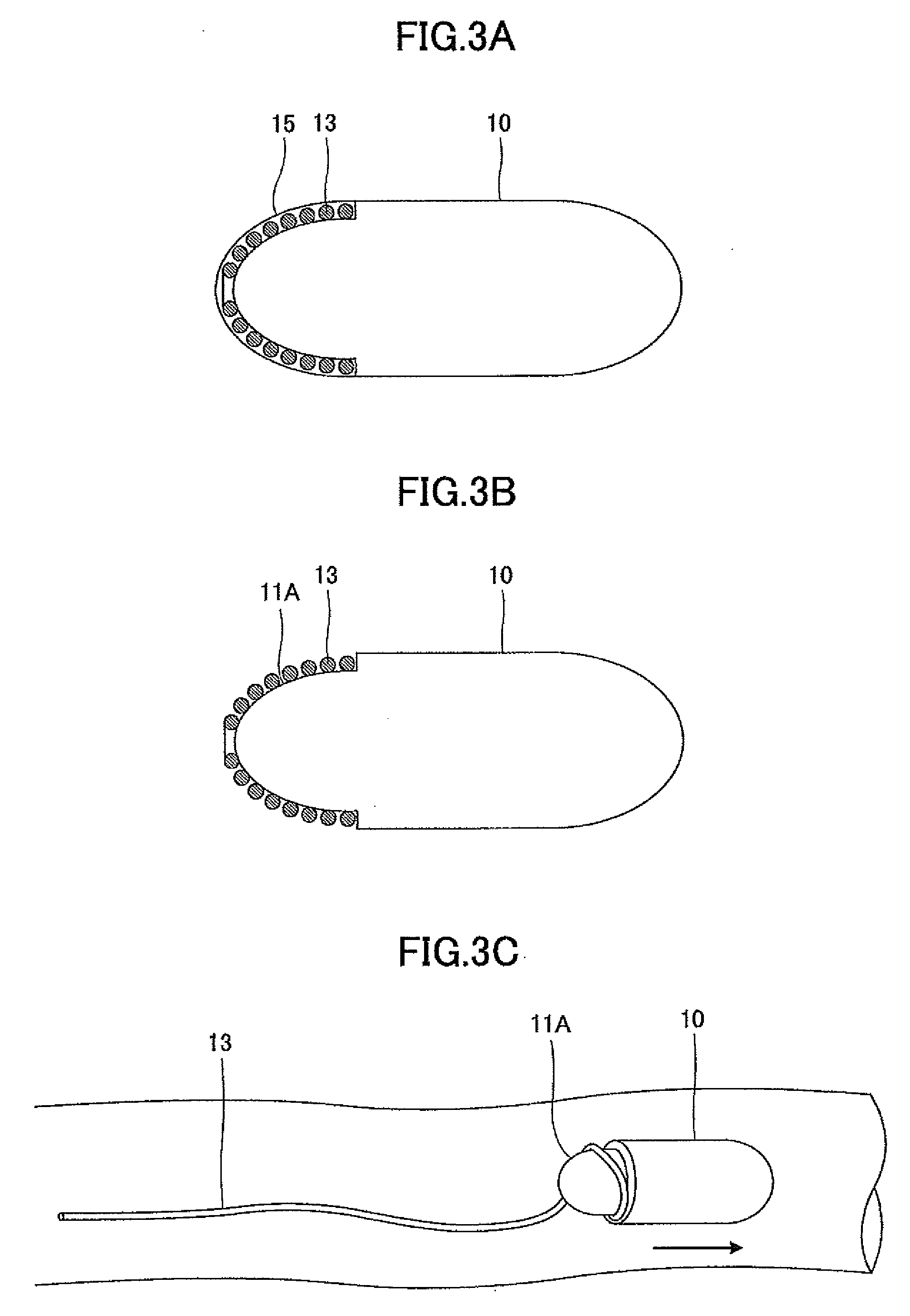
[0027]The capsule part 11 has a retracted surface 11A on which the antenna part 13 is wrapped around.
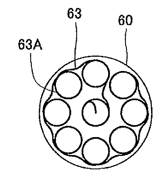
[0028]The antenna part 13 has one end thereof inserted into a hole 11b provided in the capsule part 11 for connection with a transmitter 14 provided inside the capsule 10. The remainder of the antenna part 13 is wrapped such t...
second embodiment
[0049]FIGS. 4A and 4B are drawings illustrating a medical device capsule according to a second embodiment. FIG. 4A is a perspective view, and FIG. 4B is a view illustrating a state in which the antenna is extended. A capsule 20 for use with a medical device according to the second embodiment differs from that of the first embodiment in that an anchor is provided at the tip of the antenna part 13. The remaining parts are the same as those of the first embodiment. The same elements are referred to by the same numerals, and a description thereof will be omitted.
[0050]The capsule 20 of the second embodiment has an anchor 13A at the tip of the antenna part 13. The anchor 13A serves to further extend the antenna part 13 to improve the communication conditions inside the human or animal body.
[0051]The anchor 13A may be a foldable weight made of resin, which is 3 mm long, 6 mm wide, and 6 mm high in a folded state. As the anchor 13A detaches from the capsule 20, the antenna part 13 extends....
third embodiment
[0057]FIGS. 5A and 5B are drawings illustrating a medical device capsule according to a third embodiment. FIG. 5A is a perspective view of an antenna 33 attached to a capsule 30, and FIG. 5B is a view illustrating the antenna 33 before being attached to the capsule 30.
[0058]As shown in FIG. 5A, the capsule 30 is assembled by hermetically connecting a pair of capsule parts 31 and 32. The shape of the capsule part 32 is the same as the shape of the capsule part 12 of the first embodiment. Unlike the capsule part 11 of the first embodiment, however, the capsule part 31 does not have the retracted surface 11A formed thereon. The capsule 30 is 20 mm in length and 6 mm in diameter.
[0059]The antenna part 33 and ground part 36 are pasted onto the capsule parts 32 and 31, respectively, and are covered with resin coating. The resin that coats the antenna part 33 and the ground part 36 may be polyimide, for example.
[0060]As shown in FIG. 5B, the antenna part 33 is a copper foil having a home-p...
PUM
 Abstract
Description
Claims
Application Information