System and method for facilitating target aiming and aircraft control using aircraft displays

a technology of aircraft displays and target aiming, applied in the field of display systems, can solve the problems of increasing the possibility of navigation errors, reducing the accuracy of the pilot's aim, and obscuring the targets of the pilot's flight path vector symbols, so as to facilitate target aiming and aircraft control, increase the transparency of portions, and increase the transparency of any symbol (or portion of a symbol)

Active Publication Date: 2007-10-16
HONEYWELL INT INC
View PDF9 Cites 21 Cited by
  • Summary
  • Abstract
  • Description
  • Claims
  • Application Information

AI Technical Summary

Benefits of technology

[0006]The present invention provides an improved system and method for facilitating target aiming and aircraft control by flight crews using electronic displays. In accordance with a preferred embodiment of the present invention, an aircraft display system is provided that includes a database for storing target location and boundary data, a processing unit, a position and direction determination unit for use in determining the position of an aiming symbol on a display, a graphics display generator, and a visual display. The processing unit determines whether or not a selected target to be displayed is obscured or covered by the aiming symbol to be displayed. If any portion of the target is obscured or covered by the aiming symbol, then the processing unit directs the graphics display generator to generate graphic control signals for the visual display, which increase the transparency of the portions of the aiming symbol that obscure or cover the target. Notably, in accordance with the principles of the present invention, the transparency of any symbol (or portion of a symbol) can be increased if that symbol obscures or covers a target being displayed or viewed. Thus, the present invention enhances the visibility of targets viewed using onboard visual displays, in which the targets are obscured by the symbols used to aim and control the aircraft. Advantageously, the present invention facilitates target aiming and aircraft control, which reduces pilot workload and navigation errors, and thus results in increased aircraft safety.

Problems solved by technology

Notwithstanding the distinct advantages of the use of Flight Path Vectors on aircraft displays, a significant drawback of existing aircraft displays is that the existing Flight Path Vector symbols (and other similar symbols being displayed) can obscure the targets that the pilots are attempting to see.
This loss of visual contact of the target by the pilot decreases the accuracy of the pilot's aim, and thus increases the possibility that navigation errors can occur.

Method used


Image

  • System and method for facilitating target aiming and aircraft control using aircraft displays
  • System and method for facilitating target aiming and aircraft control using aircraft displays
  • System and method for facilitating target aiming and aircraft control using aircraft displays

Examples


Embodiment Construction

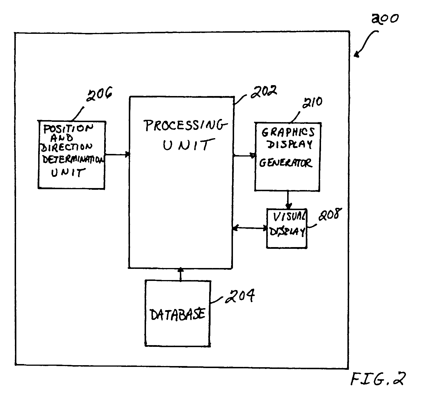
[0012]With reference now to the figures, FIG. 2 depicts a block diagram of an example system 200 for facilitating target aiming and aircraft control using an aircraft display, which can be used to implement a preferred embodiment of the present invention. For this example, system 200 includes a processing unit 202, a database 204, a position and direction determination unit 206, a visual display 208, and a graphics display generator 210. Notably, it should be understood that although system 200 appears in FIG. 2 to be arranged as an integrated system, the present invention is not intended to be so limited and can also include an arrangement whereby one or more of processing unit 202, database 204, position and direction determination unit 206, visual display 208, and graphics display generator 210 is a separate component or a subcomponent of another system located either onboard or external to an aircraft. Also, for example, system 200 can be arranged as an integrated system (e.g., ...


PUM


Abstract

An improved system and method are disclosed for facilitating target aiming and aircraft control by flight crews using electronic displays. For example, an aircraft display system is disclosed that includes a database for storing target location and boundary data, a processing unit, a position and direction determination unit for use in determining the position of an aiming symbol on a display, a graphics display generator, and a visual display. The processing unit determines whether or not a selected target to be displayed is obscured or covered by the aiming symbol to be displayed. If any portion of the target is obscured or covered by the aiming symbol, then the processing unit directs the graphics display generator to generate graphic control signals for the visual display, which increase the transparency of the portions of the aiming symbol that obscure or cover the target. Notably, the transparency of any symbol (or portion of a symbol) can be increased if that symbol obscures or covers a target being displayed or viewed. Thus, the visibility of targets viewed using onboard visual displays is significantly enhanced, whereby the targets are obscured by the symbols used to aim and control the aircraft. Advantageously, target aiming and aircraft control are facilitated, which reduces pilot workload and navigation errors, and thus results in increased aircraft safety.

Description

FIELD OF THE INVENTION[0001]The invention relates generally to the field of display systems, and more specifically, but not exclusively, to a system and method for facilitating target aiming and aircraft control using aircraft displays.BACKGROUND OF THE INVENTION[0002]Computer generated aircraft displays have become highly sophisticated and are capable of displaying a substantial amount of flight management and control information, which gives flight crews more effective control of their aircraft and helps to reduce their workload. This reduction in flight crew workload results in fewer pilot errors and thus enhances flight safety. In this regard, electronic displays, such as Heads-Up Displays (HUDs) and Heads-Down Displays (HDDs), are used in aircraft as Primary Flight Displays (PFDs) to display important flight management and control information to flight crews.[0003]Flight Path Vectors are known and widely used in HUDs and HDDs in PFDs. A Flight Path Vector (also known as a Fligh...

Claims


Application Information

Patent Timeline
Patent Type & Authority Patents(United States)
IPC IPC(8): G01C23/00
CPCG01C23/005G02B2027/0141
Inventor HE, GANG
Owner HONEYWELL INT INC
Why Eureka
Try Eureka