
Variable focus liquid lens

a liquid lens and variable focus technology, applied in the field of variable focus liquid lens, can solve the problems of large lens volume, high cost, and sensitive to vibration, and can not easily keep the periphery of the elastic membrane parallel

Active Publication Date: 2006-07-27
UNIV OF CENT FLORIDA RES FOUND INC
View PDF9 Cites 122 Cited by
  • Summary
  • Abstract
  • Description
  • Claims
  • Application Information

AI Technical Summary

Benefits of technology

[0007] The first objective of the present invention is to provide a simple liquid lens with a variable focal length.
[0009] The third objective of the present invention is to produce a tunable-focus liquid lens with high transparency, sharp and clean image, high resolution, and aberration-free.
[0011] The fifth objective of the present invention is to provide a method for making a zoom lens system using two or more of the liquid lenses of the present invention. The zoom lens does not require adjusting the distance between the lenses. Rather, the tenability is achieved by controlling the diameter of the liquid lens.
[0013] The seventh objective of the present invention is to provide a large aperture eyeglass with simple focus control. This feature allows the eyeglass wearer to conveniently adjust the diopter or power of the lens.

Problems solved by technology

The shortcoming of this kind of liquid lenses is that one can not easily keep the periphery of the elastic membrane parallel to that of the rigid lens or planar substrate during the distance change.
Moreover, the operating system for tuning the focus is complicated.
For the lenses operating by injecting or pumping liquid into the body of the lens, a complicated control system is usually needed; thus such lenses are bulky, expensive and sensitive to vibration.
The drawback of this kind of lens is that the control system used to change its diameter is complicated.
The process for changing the focal length is quite complicated and sometimes inefficient.
Usually the voltage applied to the liquid lens is very high (>200 volts) so that the power consumption is high.
Power consumption is an important issue for portable devices as it is determined by battery life.
The lens structure and the power supply system are complicated and expensive.

Method used


Image

  • Variable focus liquid lens
  • Variable focus liquid lens
  • Variable focus liquid lens

Examples


example 1

EXAMPLE 1

CONVEX / CONCAVE LENS STRUCTURE

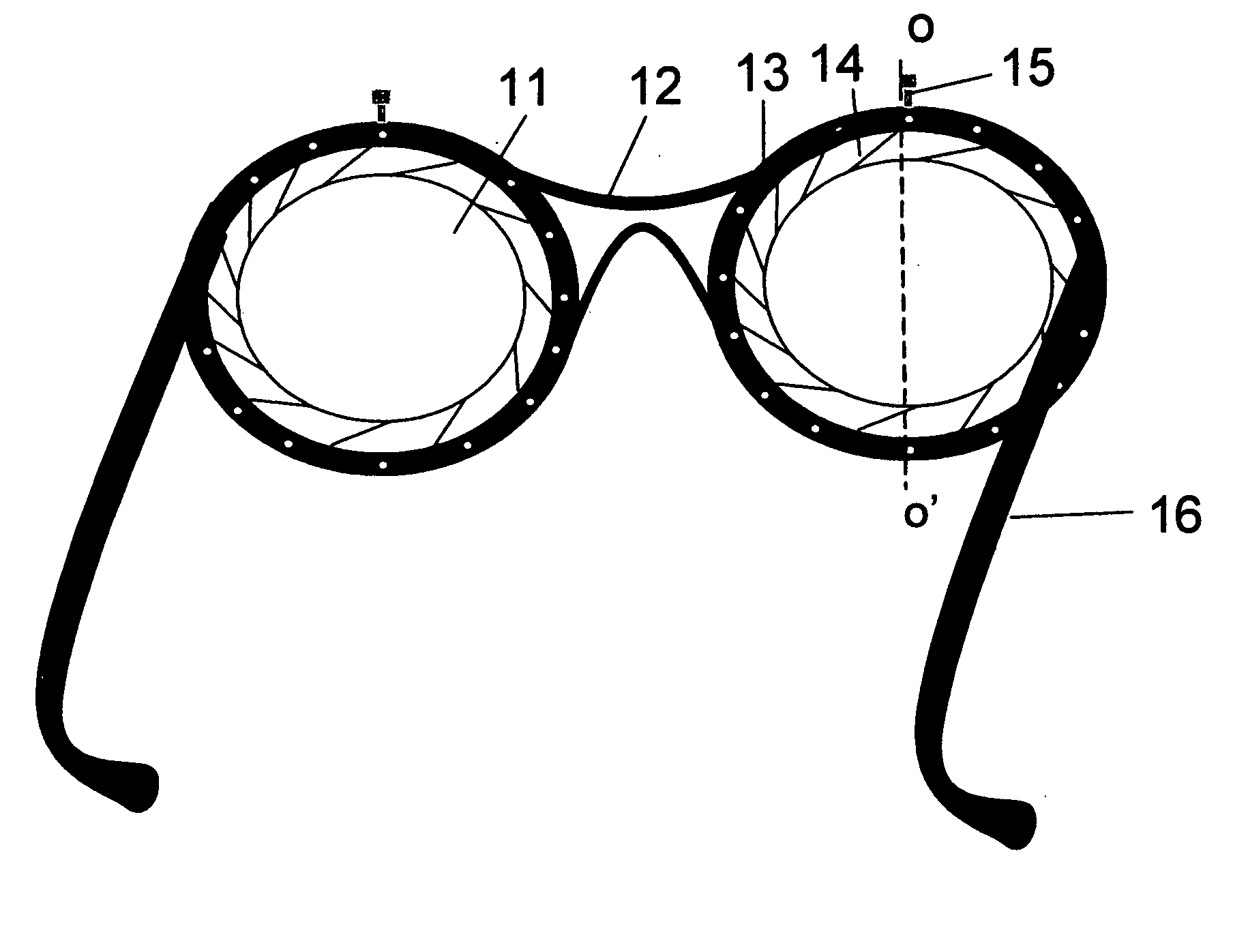
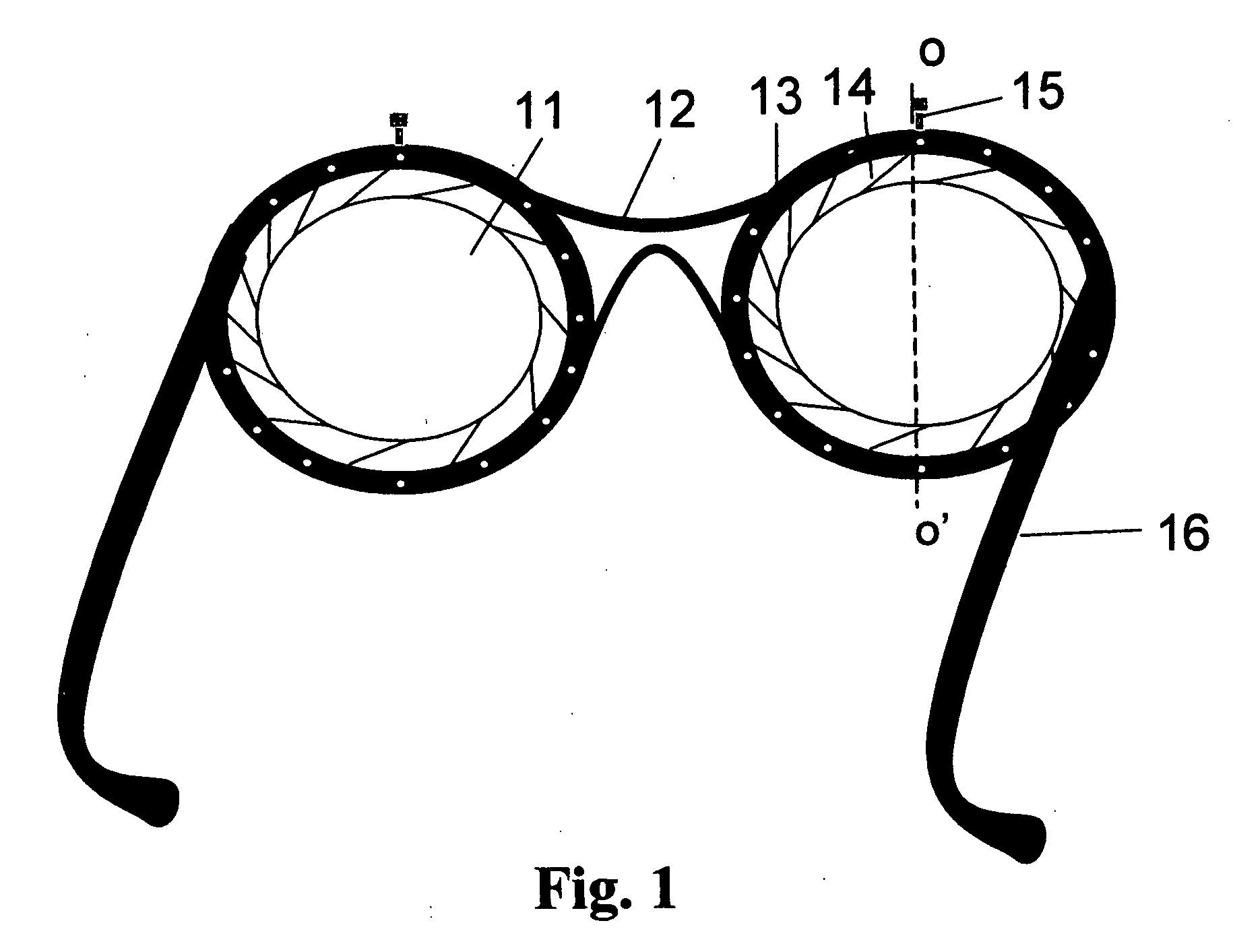
[0060]FIG. 1 shows a pair of spectacles using variable focus lenses according to the present invention, viewed from the wearer's side of the glasses. A unique feature of the spectacles or glasses is the lens cells. A fixed volume of clear liquid stored between the rigid substrate and the elastic membrane is sealed at the periphery edges of the substrates. The volume of the liquid can be changed significantly depending upon the thickness and size of the lens cell. The clear liquid can be water, ethanol, silicone oil, or any other clear oil. A circular periphery seal, with a movable lever actuator, is sealed with a distensible membrane then the periphery seal is adhesively attached to the lens cell. The circular periphery seal resembles a conventional iris diaphragm and has an adhesively attached rotatable impeller that can be mechanically or electro-mechanically activated with a lever. Thus, the annular or circular sealing ring with the distensi...

example 2

EXAMPLE 2

LIGHT FOCUSING POWER

[0063] The variation in optical power of an elastically deformable lens can be achieved by changing its radius. To estimate the optical focusing power, we use the lens structures shown in FIG. 3 and FIG. 4, as an example. In FIG. 3, when the radius of the lens aperture is r0=2 cm and the thickness of the lens is t=3 mm, the surface of the lens is flat and there is no focus effect. When the radius of the lens is reduced to r1=1.5 cm, as shown in FIG. 4, the redistributed liquid will produce a liquid spherical cap. The height (h) and the radius (R) of the spherical cap is 0.25 cm and 8.25 cm, respectively. If the liquid is a solvent with refractive index n=1.5, then the focal length η=R / (n−1)=16.5 cm, and the optical power is about 6.1 diopters. If the radius is reduced to r1=1.75 cm and the thickness of the lens is t=4 mm, then the optical power is about 4.8 diopters.

example 3

EXAMPLE 3

ZOOM LENS USING TWO LIQUID LENSES

[0064] A zoom lens camera using two of the tunable-focus liquid lens of the present invention is fabricated. To get an upright image in the focal plane, two liquid lenses are needed. An object is placed before a first liquid lens with a positive focal length. The distance from the object to the first liquid lens is larger than its focal length, thus a small inverted image is obtained. A second liquid lens is placed behind the first liquid lens. The second liquid lens also has a positive focal length. The distance from the formed image to second lens is much larger than its focal length, thus a second smaller inverted image is formed again. After two times imaging, a smaller upright image is received on the focal plane of the camera body. Unlike a mechanical zoom lens used in a commercial camera, the distance from the first lens to the second lens is not changed in the present invention. The focal length of the second lens is tuned to be lon...


PUM


Abstract

A liquid-filled variable focus lens cell is disclosed. The liquid lens cell consists of four parts: a clear distensible membrane, a transparent wall member, liquid with a fixed volume stored in lens cell chamber, and an annular periphery sealing ring. The inner surfaces of the annular sealing ring are sealed with distensible membrane. The radius of the annular sealing ring is changeable, similar to a conventional iris diaphragm. By tuning the radius of the annular sealing ring, the stored liquid in the lens cell will be redistributed, thus change the curvature of the distensible membrane. Therefore, the liquid lens cell can cause light to converge or diverge. The liquid filled lens can be operated mechanically or automatically.

Description

[0001] This invention relates to an optical focusing system, in particular to a liquid-based lens, device, system and its associated zoom lens, device or system wherein the focal length of the lens is variable. BACKGROUND AND PRIOR ART [0002] Liquid filled lens with variable focus have been proposed over the years for eyeglasses, cameras, camcorders, telescopes, binoculars, projectors as well as other machine vision applications. According to the lens operating mechanisms and liquid lens structures mentioned in several patents, the described lenses can be separated into two types. The first type is the liquid lens having a fixed volume of clear liquid which is sandwiched between a rigid lens or a planar substrate and a thin transparent elastic membrane, as described in U.S. Pat. Nos. 5,138,494 to Kurtin; 5,526,067 to Cronin et al.; 5,999,328 to Kurtin et al.; and 6,040,947 to Kurtin et al. By moving the periphery of the elastic membrane, the liquid inside the lens assembly is redist...

Claims


Application Information

Patent Timeline
Patent Type & Authority Applications(United States)
IPC IPC(8): G02B3/12
CPCG02B3/14G02C7/085
Inventor WU, SHIN-TSONREN, HONGWEN
Owner UNIV OF CENT FLORIDA RES FOUND INC
Learn More