
A compact infrared-visible common optical path zoom optical system and target detection method

An infrared optical system and optical system technology, which is applied in the field of compact infrared-visible co-optical zoom optical system and target detection, can solve the problems that cannot meet the space volume requirements of small photoelectric platforms, zoom distortion, fixed focal length, etc., and achieve the advantage of space Effects of utilization, variable focal length, and increased precision

Active Publication Date: 2021-09-28
北京小眼探索科技有限公司
View PDF10 Cites 0 Cited by
  • Summary
  • Abstract
  • Description
  • Claims
  • Application Information

AI Technical Summary

Problems solved by technology

[0005] The purpose of the present invention is to provide a compact infrared-visible common optical path zoom optical system, which solves the problem that the traditional common optical path optical system has a large volume, fixed focal length, high cost, distortion phenomenon in zooming, and cannot meet the space volume requirements of small photoelectric platforms. The problem

Method used


Image

  • A compact infrared-visible common optical path zoom optical system and target detection method
  • A compact infrared-visible common optical path zoom optical system and target detection method

Examples


Embodiment 1

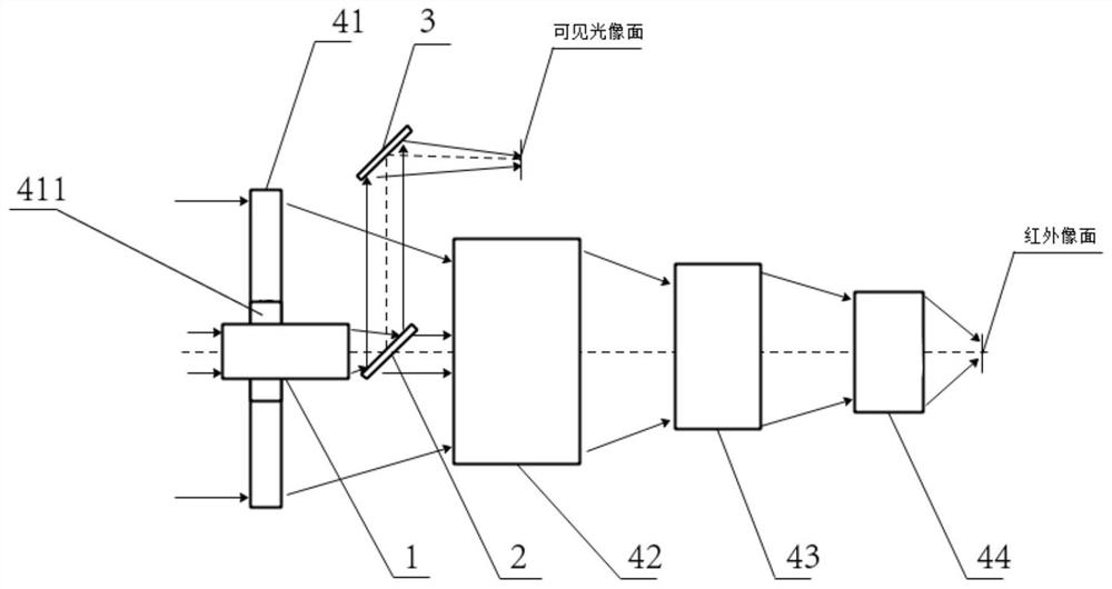
[0034] The invention discloses a compact infrared-visible common optical path zoom optical system, which includes a visible light lens group 1, a folding mirror 1, a folding mirror 2 3 and an infrared lens group 4, and the infrared lens group 4 includes sequentially arranged Infrared focusing group 41, infrared zoom lens group 42 and infrared compensating mirror group 43. The center of infrared focusing group 41 is provided with a through hole 411. Compared with the existing visible light and infrared light paths placed side by side, the optical path is designed with a circular shape. Symmetry, not only reduces the volume of the optical system, is conducive to space utilization, but also solves the problem of high cost caused by traditional beam splitters, and increases the accuracy of target detection. The visible light lens group 1 runs through the through hole 411, and the folding mirror The first 2 is located between the visible light lens group 1 and the infrared zoom lens...

Embodiment 2

[0040] The present invention also discloses a target detection method utilizing a compact infrared-visible common optical path zoom optical system, which comprises the following steps:

[0041] Step 1: Visible light and infrared light beams are incident on the optical axis of the optical system entrance;

[0042] Step 2: When the incident parallel beam of visible light passes through the visible light lens group 1, it becomes a converging beam. At this time, the converging beam is bent by 90° through the deflection mirror 1 2, and then deflected 90° by the deflection mirror 2 3, Make the image plane outside the infrared beam, perpendicular to the incident light axis, and form an image on the visible phase plane;

[0043] Step 3: After the infrared incident parallel light beam passes through the infrared optical system formed by the infrared focusing group 41, the folding mirror 1, the infrared zoom mirror group 42, the infrared compensation mirror group 43 and the infrared rea...


PUM


Abstract

The present invention provides that the present invention proposes a compact infrared-visible common optical path zoom optical system, which includes: a visible light lens group, a folding mirror 1, a folding mirror 2 and an infrared lens group, and the infrared lens group includes Infrared focusing group, infrared zoom lens group and infrared compensating mirror group, the center of the infrared focusing group is provided with a through hole, the visible light lens group runs through the through hole, and the refracting mirror is located in the visible light lens group Between the infrared zoom mirror group, the second folding mirror is located on one side of the first folding mirror, and the second folding mirror and the first folding mirror are arranged in parallel, including an infrared rear fixed group, and the infrared rear The fixed group is arranged on one side of the infrared compensation mirror group. Through the implementation of the invention, the optical path is more compact and concise, the focal length is variable, the cost is lower, and the distortion caused by the zooming process is reduced, which can meet the requirements of small photoelectric pods and other platforms for light and small composite common optical axis optical systems.

Description

technical field [0001] The invention relates to an infrared-visible common optical path zoom optical system, in particular to a compact infrared-visible common optical path zoom optical system and a target detection method. Background technique [0002] In the photoelectric detection system, the use of multi-band detection can provide more dimensional information of the target, and the combination of infrared and visible bands is a common multi-band composite detection technology. In order to obtain high-precision target position and realize high-precision image fusion and other technologies; at the same time, in order to make the compound optical system suitable for spherical hoods, the incident optical axes of the infrared and visible optical systems must be aligned to achieve common optical axis imaging. [0003] The traditional common light path optical system uses a beam splitter to achieve band splitting. The cost of the beam splitter is high, and the light splitting e...

Claims


Application Information

Patent Timeline
Patent Type & Authority Patents(China)
IPC IPC(8): G02B15/15G02B7/10
CPCG02B15/15G02B7/10
Inventor 刘相伟李卓荦
Owner 北京小眼探索科技有限公司
Learn More