Variable focal length lens apparatus and control method

a variable focal length and control method technology, applied in the field of variable focal length lens apparatus and variable focal length lens control method, can solve the problems of low processing efficiency, limited use, and high cost of computer system with high processing capability, and achieve the effects of high processing capability, reduced quality, and efficient generation

Active Publication Date: 2021-06-01
MITUTOYO CORP
View PDF13 Cites 0 Cited by
  • Summary
  • Abstract
  • Description
  • Claims
  • Application Information

AI Technical Summary

Benefits of technology

[0007]The present invention provides a variable focal length lens apparatus and variable focal length lens control method that are capable of efficiently generating a standing wave and also capable of acquiring a high-quality image.
[0009]In the present invention, a time delay element that delays the change in the frequency of the drive signal that is due to the resonance lock controller can be used as the tracking delayer, for example. Also, the change may be delayed using a limiter element that limits an amount of change or a rate of change per amount of time for the frequency of the drive signal. According to the present invention, even when the amount of change or the rate of change in the frequency of the drive signal due to the resonance lock controller is large, by delaying the change, the change can be constrained to a gentle change, and a degradation in quality due to a major change in frequency, such as flickering in a measurement image, can be avoided. As a result, in the variable focal length lens apparatus, the standing wave can be generated efficiently while obtaining a high-quality image. By using a computer system having a high processing capability for the drive controller, a processing cycle of the resonance lock controller can be sped up and, as a result, the amount of change or rate of change of the frequency per cycle can be reduced and flickering in the image or the like can be avoided. However, a computer system having a high processing capability is expensive and cannot be used readily. However, according to the present invention, flickering in an image or the like can be avoided using the tracking delayer, without speeding up the cycle of the resonance lock control, and the necessity of a computer system having a high processing capability can be eliminated, and a low-cost variable focal length lens apparatus can be readily achieved.
[0010]In the variable focal length lens apparatus according to the present invention, the tracking delayer is preferably a low-pass filter. In the present invention, a high frequency component of a change in frequency (component where a change behavior is rapid) is eliminated from a drive signal whose frequency is modified by the resonance lock controller, and only a low frequency component of the drive signal (component where the change behavior is slow) is input to the liquid lens system. The change in frequency is restricted to the low frequency component, and as a result, the drive signal that is changed by tracking to the resonance frequency of the liquid lens system is limited to gentle changes even when changes are drastic originally. Accordingly, an ability to delay changes in the drive signal can be obtained using the low-pass filter. Also, a simple configuration in which the low-pass filter is applied to the drive signal output from the resonance lock controller is sufficient as the tracking delayer, and stable functionality can be achieved at a low cost.
[0011]The variable focal length lens apparatus according to the present invention preferably includes a resonance lock console that switches the resonance lock controller between enabled and disabled, and switches the tracking delayer between enabled and disabled. In the present invention, enabling and disabling the resonance lock controller can be selected at any time, and also enabling and disabling the tracking delayer can be selected at any time while the resonance lock controller is enabled, and an operator can achieve a desired display while observing image quality.
[0012]A control method of a variable focal length lens apparatus according to the present invention uses a liquid lens system in which the refractive index changes in accordance with an input drive signal and a drive controller that outputs the drive signal to the liquid lens system. The method performs resonance lock control that causes the drive signal to track to a resonance frequency of the liquid lens system, and also delays a change in the frequency of the drive signal when an amount of change in the frequency of the drive signal that is due to the resonance lock control exceeds a predetermined limit value. In the present invention, the effects described for the above-mentioned variable focal length lens apparatus according to the present invention can be obtained.
[0013]The present invention can provide a variable focal length lens apparatus and variable focal length lens control method that are capable of efficiently generating a standing wave and also capable of acquiring a high-quality image.

Problems solved by technology

However, a computer system having a high processing capability is expensive and cannot be used readily.
The change in frequency is restricted to the low frequency component, and as a result, the drive signal that is changed by tracking to the resonance frequency of the liquid lens system is limited to gentle changes even when changes are drastic originally.

Method used


Image

  • Variable focal length lens apparatus and control method
  • Variable focal length lens apparatus and control method
  • Variable focal length lens apparatus and control method

Examples


Embodiment Construction

[0021]The particulars shown herein are by way of example and for purposes of illustrative discussion of the embodiments of the present invention only and are presented in the cause of providing what is believed to be the most useful and readily understood description of the principles and conceptual aspects of the present invention. In this regard, no attempt is made to show structural details of the present invention in more detail than is necessary for the fundamental understanding of the present invention, the description taken with the drawings making apparent to those skilled in the art how the forms of the present invention may be embodied in practice.

[0022]Hereafter, an embodiment of the present invention is described with reference to the drawings.

Variable Focal Length Lens Apparatus 1

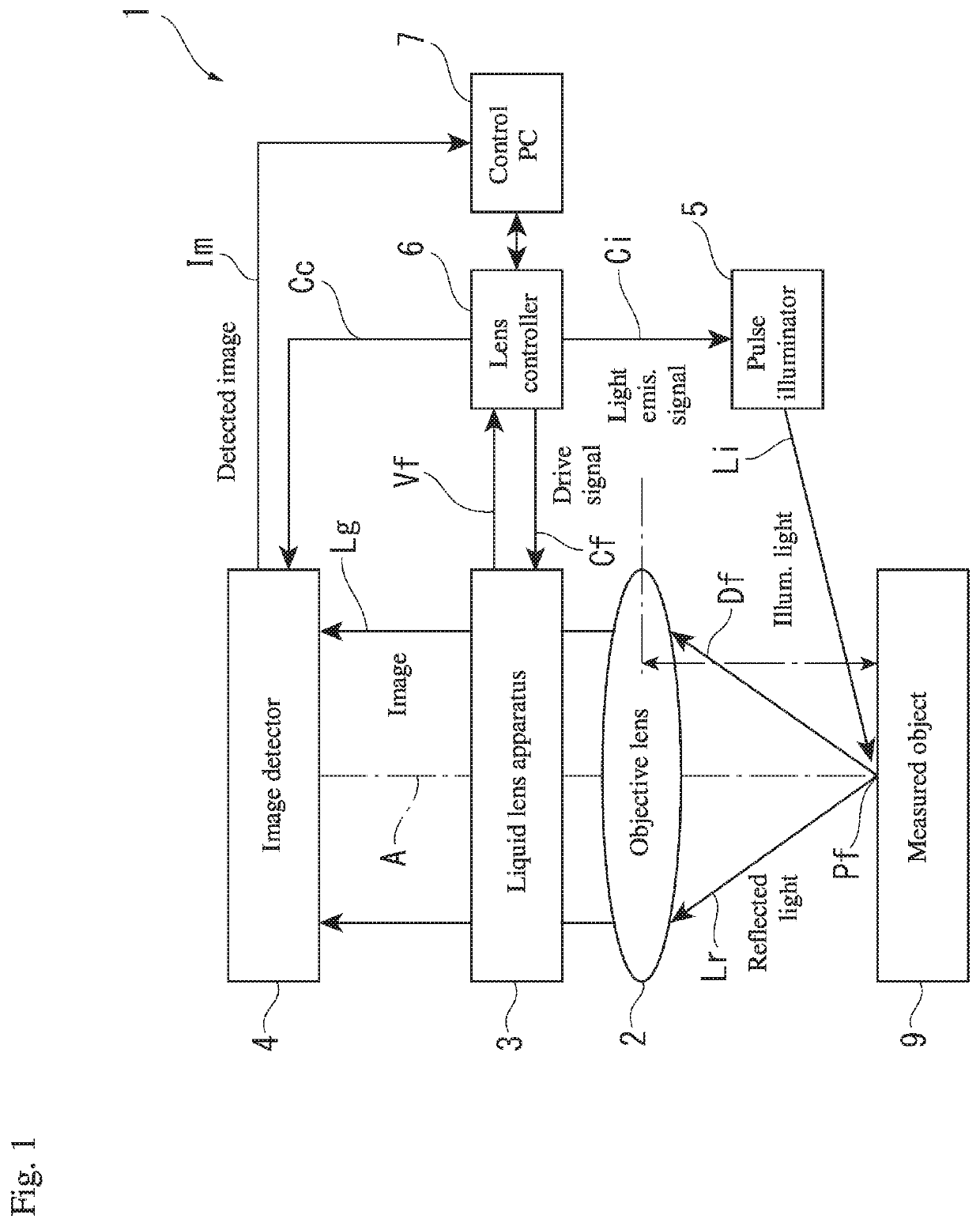
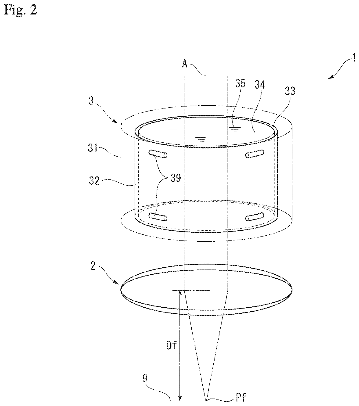
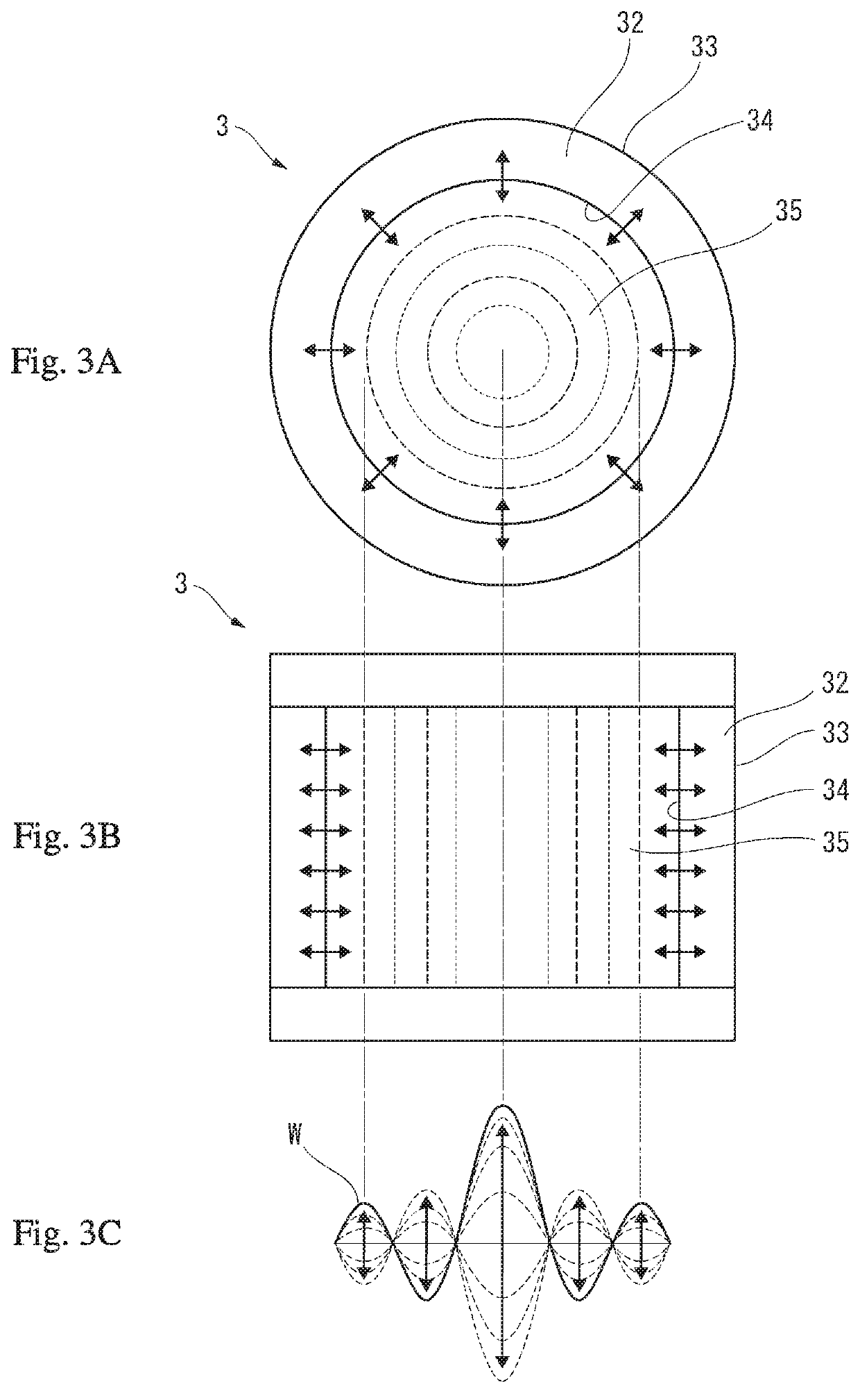
[0023]In FIG. 1, a variable focal length lens apparatus 1 detects an image of a surface of a measured object 9 while varying a focal length. In order to do this, the variable focal length lens ...


PUM


Abstract

A variable focal length lens apparatus includes a liquid lens apparatus in which the refractive index changes in accordance with an input drive signal, and a drive controller that outputs the drive signal to the liquid lens apparatus. The drive controller includes a resonance lock controller that changes a frequency of the drive signal by tracking the drive signal to a resonance frequency of the liquid lens apparatus, and a tracking delayer that delays a change in the frequency of the drive signal that is due to the resonance lock controller.

Description

CROSS-REFERENCE TO RELATED APPLICATIONS[0001]The present application claims priority under 35 U.S.C. § 119 of Japanese Application No. 2018-161550, filed on Aug. 30, 2018, the disclosure of which is expressly incorporated by reference herein in its entirety.BACKGROUND OF THE INVENTION1. Field of the Invention[0002]The present invention relates to a variable focal length lens apparatus and a variable focal length lens control method.2. Description of Related Art[0003]As a variable focal length lens apparatus, an apparatus has been developed that uses a liquid lens system (hereafter referred to simply as “lens system”) operating on a principle described by the specification of U.S. Published Patent Application No. 2010 / 0177376, for example. The liquid lens system is formed by immersing in transparent liquid a hollow cylindrical oscillating member that is formed of a piezoelectric material. In the liquid lens system, when AC voltage is applied to an inner circumferential surface and ou...

Claims


Application Information

Patent Timeline
Patent Type & Authority Patents(United States)
IPC IPC(8): G02B3/14G02B15/14G02B7/02
CPCG02B3/14G02B15/14G02B7/02G02B26/004G02B21/0016G02B21/241G02F1/33G02F1/294
Inventor IGASAKI, SHIROOOBA, NOBUO
Owner MITUTOYO CORP
Why Eureka
Try Eureka