
Methods and systems for the identification of circuits and circuit designs

a technology applied in the field of methods and systems for the identification of circuits and circuit designs, can solve problems such as difficult detection of identification labels, and achieve the effect of maintaining the correctness and functionality of designs and minimising hardware overhead

Inactive Publication Date: 2006-03-21
RGT UNIV OF CALIFORNIA
View PDF5 Cites 130 Cited by
  • Summary
  • Abstract
  • Description
  • Claims
  • Application Information

AI Technical Summary

Benefits of technology

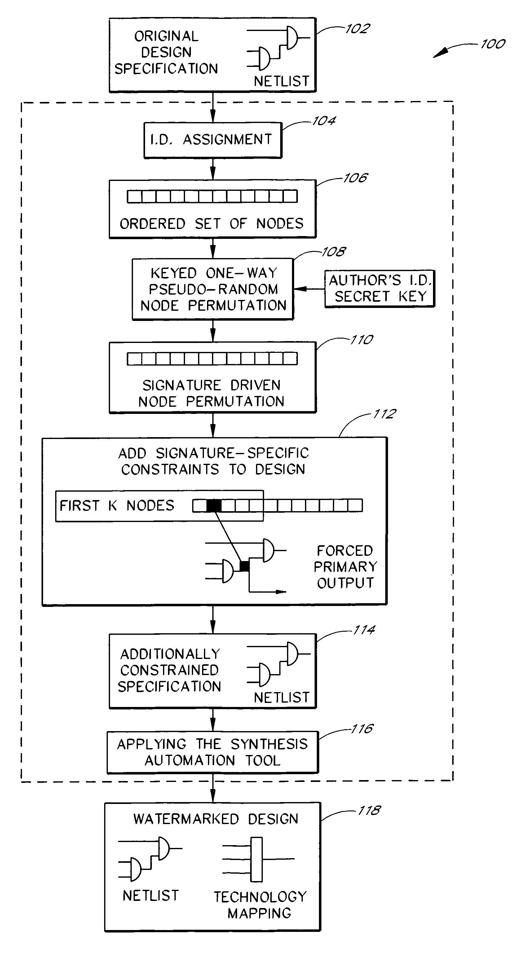
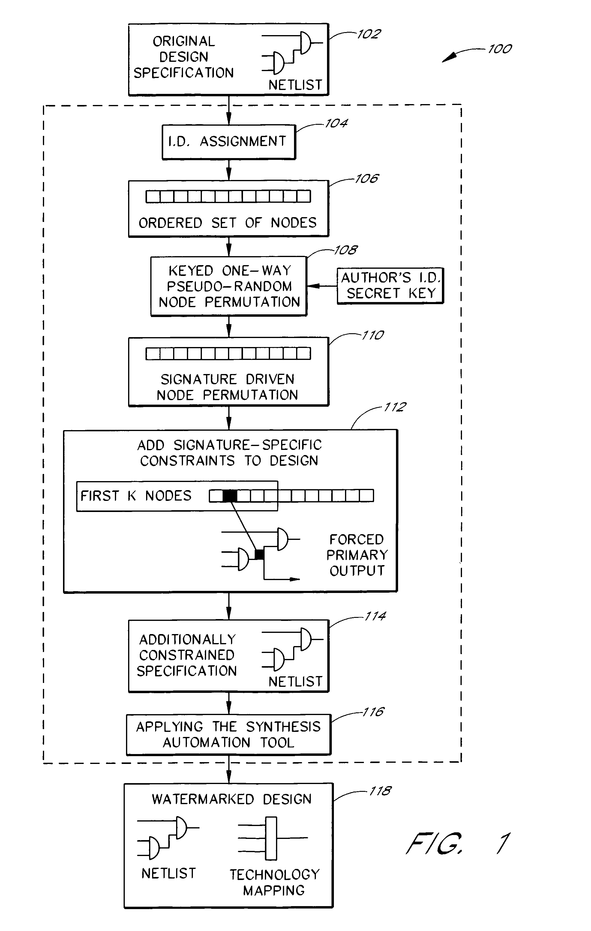
The present invention relates to protecting intellectual property, such as circuit designs, software, and databases, from unauthorized use and modification. The invention provides a method of embedding an identifier in the design to identify the source or author of the design. The identifier is embedded by adding or superimposing constraints on the design specification, resulting in a modified specification that still performs the specified function. The identifier can be embedded at various stages of the design process, such as the logic minimization phase, allocation phase, transformation phase, and partitioning phase. The invention also allows for the embedding of multiple identifiers in a circuit design and can be used in software or hardware specification languages. Overall, the invention provides a way to protect and manage intellectual property.

Problems solved by technology

In one embodiment, the identifier is difficult to detect.

Method used


Image

  • Methods and systems for the identification of circuits and circuit designs
  • Methods and systems for the identification of circuits and circuit designs
  • Methods and systems for the identification of circuits and circuit designs

Examples


case 1

[0139]The following scenario illustrates how successful watermarking tampering is substantially prevented. Alice has a design which is watermarked using the watermarking techniques described above. Bob purchases the design from Alice. There are at least three cases to consider, as discussed below.[0140] Bob analyzes the design and tries to find some artifact or “ghost signature” he can claim is his signature, as illustrated in FIG. 9a. That is, Bob may attempt to find a “signature” corresponding to a set of constraints with a favorable Pc, but which was discovered after the fact, rather than being intentionally added to the design as a watermark. Bob claims that the design is his because the design contains his, as well as Alice's, signatures. In this case, the longer and stronger signature will be a considered to be the real signature. Because it would be a very difficult task for an unauthorized user or claimant, such as Bob, to “find” any meaningful signature from the design, Ali...


PUM


Abstract

The present invention is related to systems and methods for adding a signature to circuit design. In one embodiment, a first set of constraints used to specify a functional portion of the circuit design is received. A second set of constraints used to specify the signature is received as well. The circuit design is generated based on at least the first constraints and the second constraints, wherein the signature is embedded in the functional portion.

Description

[0001]The present application claims priority from U.S. Provisional Patent Application No. 60 / 125,286, filed on Mar. 19, 1999, U.S. Provisional Patent Application No. 60 / 125,275, filed on Mar. 19, 1999, and U.S. Provisional Patent Application No. 60 / 129,135, filed on Apr. 13, 1999. The contents of these applications, in their entirety, is hereby incorporated by reference.BACKGROUND OF THE INVENTION[0002]1. Field of the Invention[0003]The present invention relates to methods and systems for the identification of circuits and circuit designs, and in particular, to placing identifiers in circuits and circuit designs.[0004]2. Description of the Related Art[0005]Intellectual property is playing an increasingly important role in the development and economy of modern societies. By way of example, intellectual property includes such essential areas as software, hardware, circuit designs, biotechnology, and media, such as television, cinema, music, books, and magazines. The increase in impor...

Claims


Application Information

Patent Timeline
Patent Type & Authority Patents(United States)
IPC IPC(8): H04L9/00G06F9/45
CPCG06T1/0021H04L9/3247H04L2209/608H04L2209/34
Inventor POTKONJAK, MIODRAG
Owner RGT UNIV OF CALIFORNIA
Learn More