Four-phase dual pumping circuit

a dual-phase pumping and circuit technology, applied in the field of four-phase dual-phase pumping circuits, can solve the problems of increasing back-bias between the source and the diode connected transistor, the charge pump transistors would no longer switch properly, and the conventional charge pump would have difficulty dealing with the lower battery voltage being used, etc., to achieve the effect of maximizing output voltage, minimizing the body effect of main pass transistors, and efficient generation of high positive and negative voltages

Inactive Publication Date: 2005-10-04
EMEMORY TECH INC
View PDF9 Cites 131 Cited by
  • Summary
  • Abstract
  • Description
  • Claims
  • Application Information

AI Technical Summary

Benefits of technology

[0011]It is another objective of the claimed invention to provide four-phase dual pumping circuits that efficiently generates the required high positive and high negative voltages using the same triple-well technology at a low supply voltage.
[0012]It is another objective of the claimed invention to provide a four-phase dual pumping circuit that minimizes the body effect of the main pass transistors so the output voltage is maximized.
[0013]It is another objective of the claimed invention to provide a four-phase dual pumping circuit that avoids p-n junction conduction.

Problems solved by technology

A major problem is that conventional charge pumps have difficulty dealing with the lower battery voltages being used.
The problem is related to the fact that diode-connected transistors develop increasing back-bias between the source and the body of the transistor as the voltage increases along the length of the pump.
With increased effective transistor thresholds and decreased supply voltages, the charge pump transistors would no longer switch properly and the charge pump would not work.
Applying a uniform high clock voltage, generated by bootstrapping, leads to energy inefficiency because the greater the current delivered by the clocking voltage, the less efficient the bootstrapping operation.
In the latter stages where high voltages are required, this inefficiency was unavoidable.
In the initial stages of the charge pump, where as high a voltage is not needed, the clock bootstrapping operation was inefficient.
In general, currently available charge pumps are inefficient, large, and complex.
They do not properly deal with low initial supply voltages and fail to address the problems inherent with higher threshold voltages caused by the body effect.

Method used


Image

  • Four-phase dual pumping circuit
  • Four-phase dual pumping circuit
  • Four-phase dual pumping circuit

Examples


Embodiment Construction

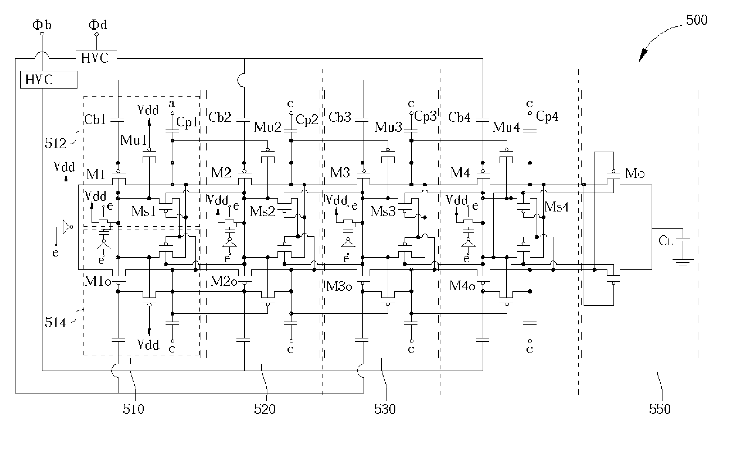
[0034]Please refer to FIG. 5 which shows the circuit design of the dual pumping circuit according to one embodiment of the present invention. The dual pumping circuit is suitable for many different electrical devices and the focus of the embodiments will be on memory devices which are well known to those skilled in the art. Positive dual pumping circuit 500 comprising a plurality of PMOS, shown in FIG. 5, is illustrated with 4 stages, wherein each stage is further described in details in FIGS. 8–13 where the operation of each stage is described. The dual pumping circuit 500 shown in this embodiment is exemplified by a four-phase four-stage positive charge dual pumping circuit but the number of phases and stages is not limited to what is disclosed by the present invention and can be altered according to the spirit of the present invention.

[0035]The dual pumping circuit 500 comprises four serially linked stages 510, 520, 530, and 540 for achieving the required output voltage Vout from...


PUM


Abstract

A four-phase dual pumping circuit has a number of stages according to the required output voltage based on an input voltage. Each stage has a first pumping unit and a second pumping unit that are mirror and identical to each other and electrically coupled to each other. The dual pumping circuit is controlled by four-phase clocks which are made from one pair of out of phase clocks. The transistors of the dual pumping circuit have special substrate connection to minimize body effects. The four-phase dual pumping circuit uses NMOSFETS for negative pumping and PMOSFETS for positive pumping.

Description

BACKGROUND OF INVENTION[0001]1. Field of the Invention[0002]The invention generally relates to charge pumps, and more particularly, to methods and apparatus for generating a high positive or a negative voltage for memory devices.[0003]2. Description of the Prior Art[0004]The era of digital information has arrived which pushed the development of electronic information processing devices such as computers, wireless devices, personal digital assistants (PDAs), portable multimedia players / recorders, and the like in the recent years. One crucial component to any electronic information processing device is the memory device which has gone under substantial advancement. The performance in speed and reliability along with the size and packaging of these memory devices have greatly improved as a result smaller and faster memory devices are continuously being introduced to the market.[0005]In order to reduce power consumption and extend battery life, much of the integrated circuitry such as m...

Claims


Application Information

Patent Timeline
Patent Type & Authority Patents(United States)
IPC IPC(8): G05F3/02G05F1/10H02M3/07
CPCH02M3/073H02M2003/075H02M2003/077H02M3/075H02M3/077
Inventor LIN, HONG-CHINHSIEH, MING-CHIHLU, JAIN-HAOHO, CHIEN-HUNG
Owner EMEMORY TECH INC
Why Eureka
Try Eureka