Liquid-crystal lens system and forming method

A liquid crystal lens and liquid crystal layer technology, which is applied to lenses, optics, instruments, etc., can solve the problems of complex manufacturing technology and limited zoom range, and achieve the effects of wide zoom range, low cost, and variable focal length.

Inactive Publication Date: 2009-11-18
HONG FU JIN PRECISION IND (SHENZHEN) CO LTD +1
View PDF4 Cites 0 Cited by
  • Summary
  • Abstract
  • Description
  • Claims
  • Application Information

AI Technical Summary

Problems solved by technology

The lenses with the above structures are all refraction liquid crystal lenses, and the zoom range is limited, and the manufacturing technology of some devices is relatively complicated.

Method used


Image

  • Liquid-crystal lens system and forming method
  • Liquid-crystal lens system and forming method
  • Liquid-crystal lens system and forming method

Examples


Embodiment Construction

[0015] The present invention will be further described in detail below in conjunction with the accompanying drawings.

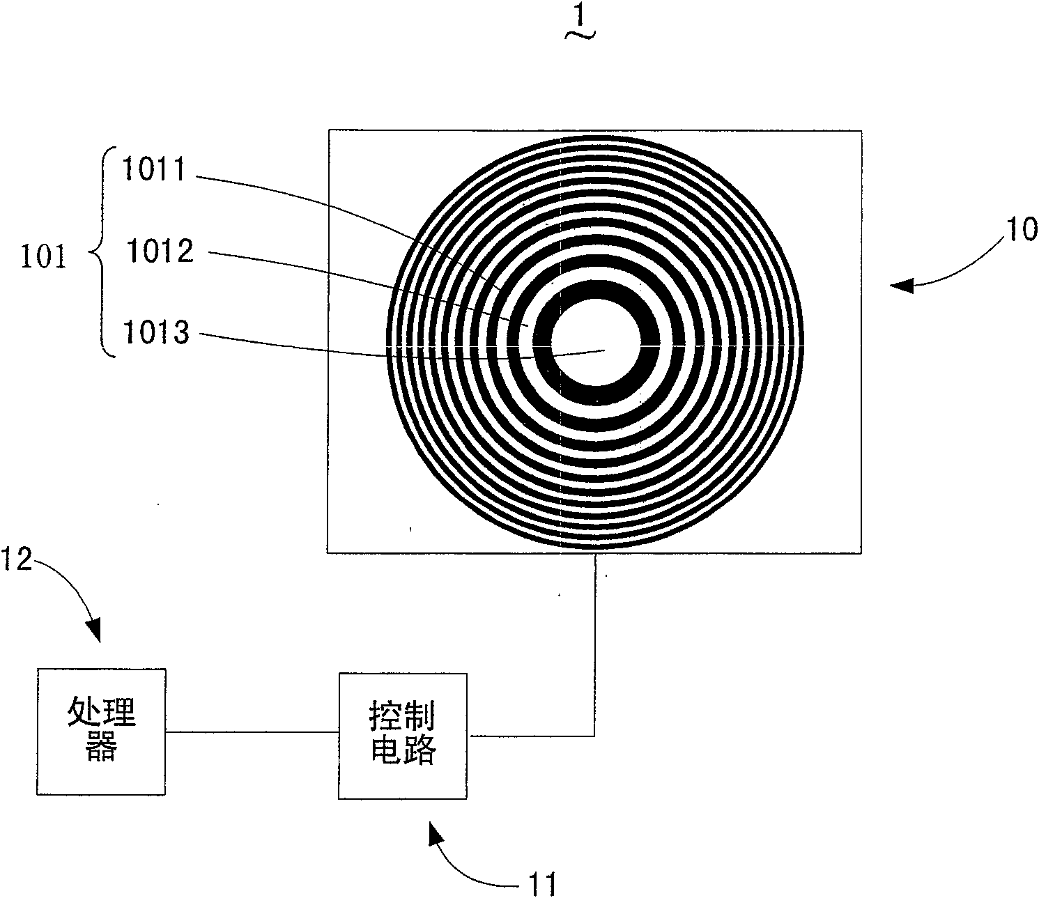
[0016] see figure 1 , is an embodiment of the liquid crystal lens system of the present invention.

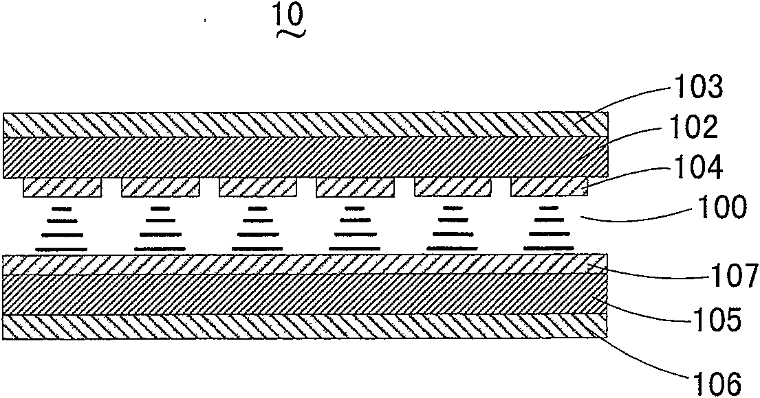
[0017] The liquid crystal lens system 1 includes a processor 12 , a control circuit 11 and a liquid crystal panel 10 .

[0018] The processor 12 is used to calculate and generate the pattern to be displayed by the liquid crystal panel 10 when the liquid crystal lens system 1 is working, and transmit the pattern information to the control circuit 11 . The pattern of this embodiment is a Fresnel concentric ring pattern, that is, a group of concentric rings with alternating light and dark.

[0019] One end of the control circuit 11 is connected to the processor 12 to receive the pattern information generated by the processor 12 through calculation. The other end of the control circuit is connected to the liquid crystal panel 10 for transmitting the pattern inf...


PUM


Abstract

The present invention relates to a liquid crystal lens system, which comprises a liquid crystal panel with a plurality of pixels, the liquid crystal panel is formed with a Fresnel concentric annular band diffraction fringe pattern, and the Fresnel concentric annular band diffraction fringe pattern is formed by the composed of pixels. The pattern on the liquid crystal panel is controlled and adjusted by a processor and a control circuit, so that it presents a variable Fresnel concentric annular band diffraction fringe pattern, thereby becoming a diffractive lens with adjustable focal length. The liquid crystal lens system has the advantages of simple structure, low cost, large focal length range, and can realize the functions of eccentricity compensation and beam shaping by adjusting the pattern on the liquid crystal panel. The present invention also relates to a method for forming a liquid crystal lens.

Description

【Technical field】 [0001] The invention relates to an optical lens, in particular to a liquid crystal lens system. 【Background technique】 [0002] Lenses are basic optical components that can be found everywhere in optical instruments and equipment. With the development of optical technology, the requirements for lenses are getting higher and higher: continuously variable focal length of lenses, lenses with large focal lengths, and small aberrations. Either way, meeting the requirements will make the optical system large and complex. [0003] Microlens is also an important optical device. At present, the traditional manufacturing methods mainly include particle exchange method, compression molding method, photosensitive glass thermoforming method and photoresist thermoforming method. Due to the limitations of the materials used and the traditional technology, the microlenses made by these methods have a common feature, that is, the lens has only one focal length. To obtain...

Claims


Application Information

Patent Timeline
Patent Type & Authority Patents(China)
IPC IPC(8): G02F1/13G09G3/36G02B3/08G02B5/18
Inventor 张维中
Owner HONG FU JIN PRECISION IND (SHENZHEN) CO LTD
Why Eureka
Try Eureka