Zero insertion force cable interface

a zero-inserting force, cable interface technology, applied in the direction of coupling contact members, coupling device connections, instruments, etc., can solve the problems of affecting the accuracy of positioning of the probe pin

Active Publication Date: 2007-11-06
OHIO ASSOCD ENTERPRISES
View PDF13 Cites 13 Cited by
  • Summary
  • Abstract
  • Description
  • Claims
  • Application Information

AI Technical Summary

Problems solved by technology

However, for some testing applications many pins, i.e., 1,000 pins or more, are required, making the forces normal to the probe board substantial.
Deflection of the probe board caused by the total compressive force of the pogo pins will cause the probe pins to move and possibly lose their accurate positioning.

Method used


Image

  • Zero insertion force cable interface
  • Zero insertion force cable interface
  • Zero insertion force cable interface

Examples


Embodiment Construction

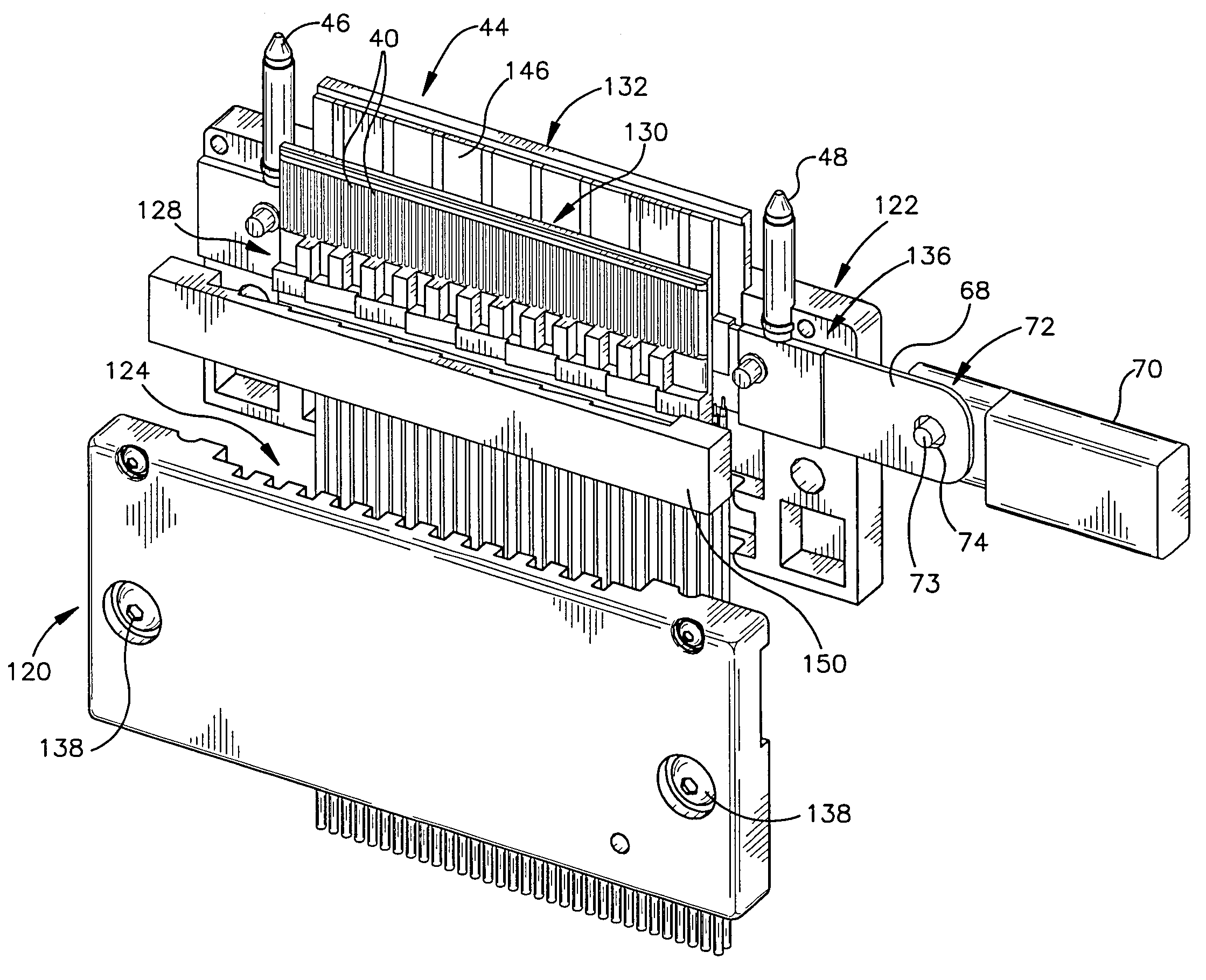
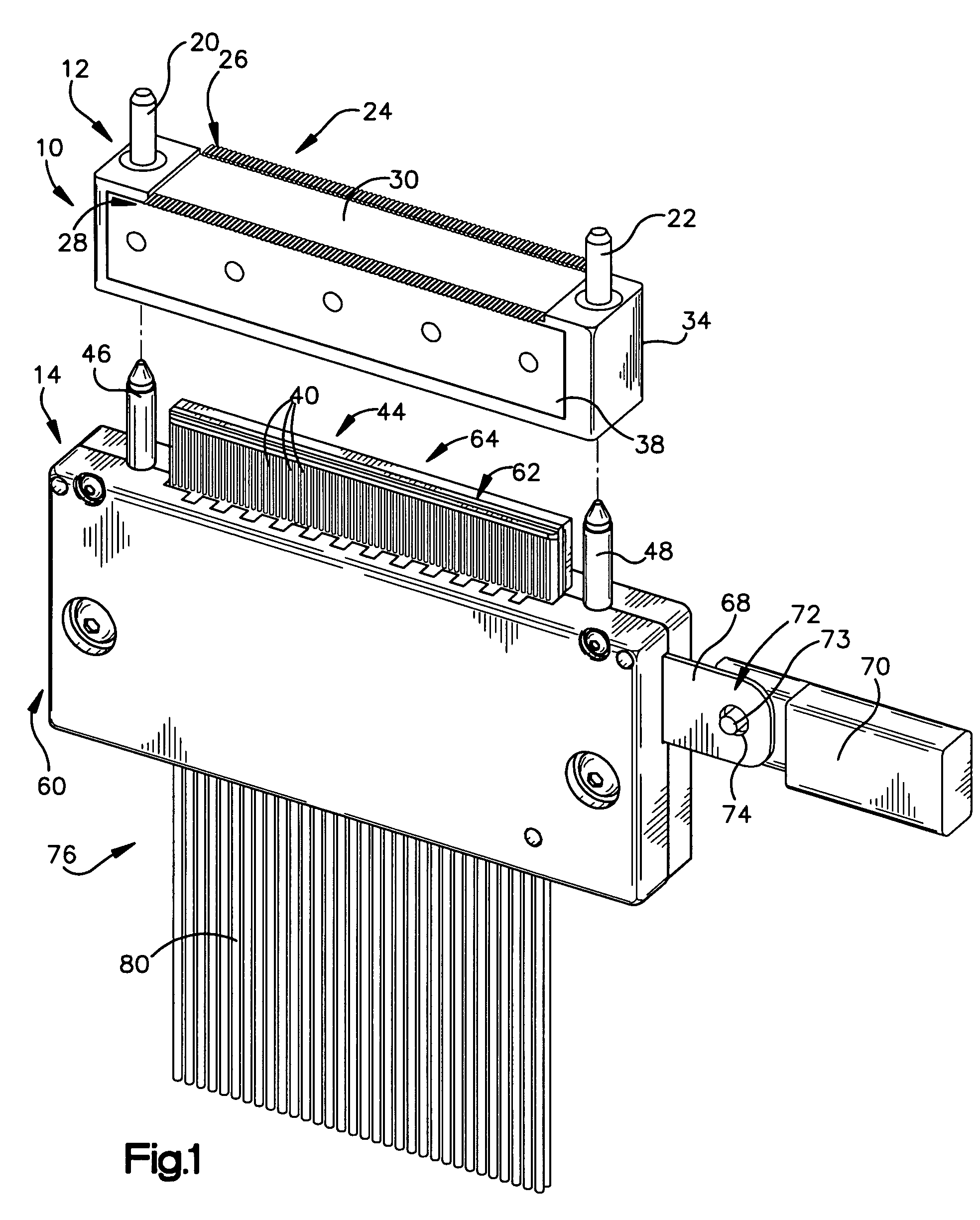
[0028]A connector assembly includes a female dual row connector, and a male dual row connector configured to be inserted into the female dual row connector. The female connector is configured to be compression mounted onto a circuit board, and has conductive tails for being brought into contact with traces on the card or circuit board. The female connector may have a stiffener to resist bowing in the connector caused by the reaction force of the compressive contact tails on the board. The rows of contacts of the male connector may be selectively brought together (collapsed) or moved apart (expanded). The rows of contacts are collapsed during insertion or removal of the male connector from the female connector, thus allowing zero force insertion of the male connector into the female connector. The collapsing and expanding of the rows for the male connector may be accomplished through any of a variety of mechanisms.

[0029]Referring to FIG. 1, a connector assembly 10 includes a female c...


PUM


Abstract

A connector assembly includes a female dual row connector, and a male dual row connector configured to be inserted into the female dual row connector. The female connector is configured to be compression mounted onto a circuit card, and has conductive tails for being brought into contact with traces on the card or circuit board. The female connector may have a stiffener to help it maintain its shape. The rows of contacts of the male connector may be selectively brought together (collapsed) or moved apart (expanded). The rows of contacts are collapsed during insertion or removal of the male connector from the female connector, thus allowing zero force insertion of the male connector into the female connector. The collapsing and expanding of the rows for the male connector may be accomplished through any of a variety of mechanisms.

Description

[0001]This application claims the benefit of U.S. Provisional Application No. 60 / 587,447, filed Jul. 13, 2004, which is hereby incorporated by reference in its entirety.BACKGROUND OF THE INVENTION[0002]1. Technical Field of the Invention[0003]This invention relates to electrical connectors, and to methods for coupling together and de-coupling electrical connectors.[0004]2. Description of the Related Art[0005]In the field of silicon chip testing, probe cards with multiple probes attached have been used to contact specific, accurately-located probe points on the chip. Multiple transmission line cables have been used to communicate the probe-board positions with an attendant test computer. Typically, the interface between the test computer and the probe card has been a multiplicity of spring pins (commonly referred to as “pogo pins”) positioned to engage the probe board in compression, and coupled to the transmission lines to the cable. However, for some testing applications many pins,...

Claims


Application Information

Patent Timeline
Patent Type & Authority Patents(United States)
IPC IPC(8): H01R13/15H01R13/62
CPCH01R12/79H01R12/7047H01R13/629G01R1/0408G01R31/2889H01R13/512H01R2201/20
Inventor CROFOOT, LARRY M.ROATH, ALAN L.VENALECK, JOHN T.
Owner OHIO ASSOCD ENTERPRISES
Why Eureka
Try Eureka