
Method and system for compensating residual dispersion curvature

a dispersion curve and residual technology, applied in the field of residual dispersion curve compensation, can solve the problems of limiting the ability to transmit high data rates, affecting the ability to produce dcf that simultaneously compensates the dispersion slope, and the overall propagation penalty proportional to the square of bit ra

Inactive Publication Date: 2007-11-06
CIENA
View PDF7 Cites 15 Cited by
  • Summary
  • Abstract
  • Description
  • Claims
  • Application Information

AI Technical Summary

Problems solved by technology

Dispersion has a limiting effect on the ability to transmit high data rates.
Thus, the combination of increasing spectral broadening and decreasing distortion tolerance makes the overall propagation penalty proportional to the square of bit rate.
While DCF provides adequate levels of dispersion compensation, it is difficult to produce DCF that also simultaneously compensates the dispersion slope.
Uncompensated dispersion slope results in system penalty and can significantly shorten transmission distances and / or channel counts.
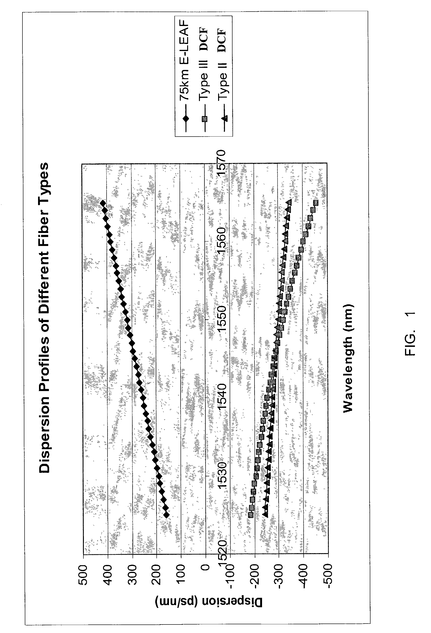
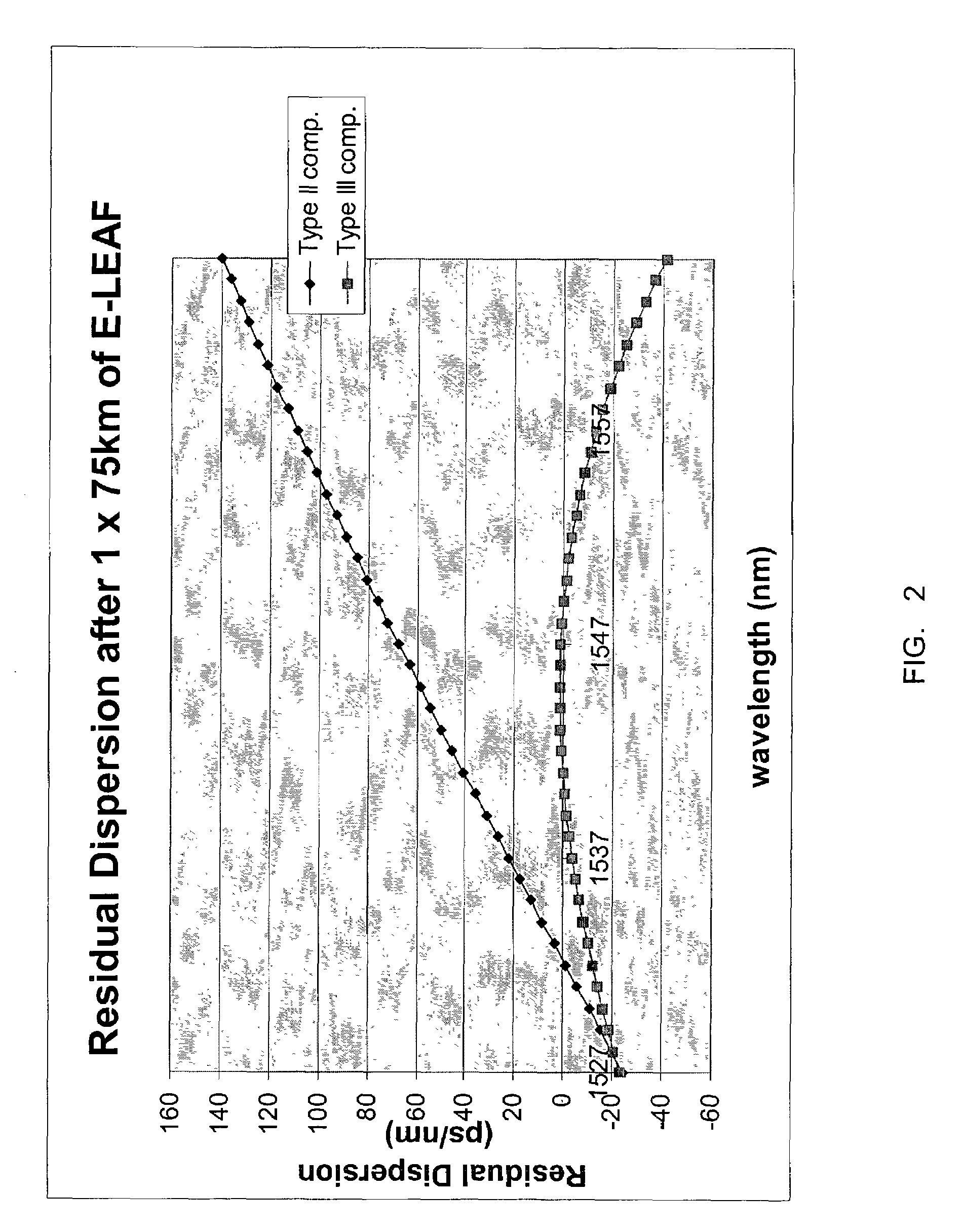
Unfortunately, this high level of dispersion slope compensation can introduce residual dispersion curvature. FIG. 1 is a graph of dispersion versus wavelength for a transmission fiber (referenced as E-LEAF), a first type of DCF (referenced as Type II DCF) and a second type of DCF (referenced as Type III DCF).
This gives rise to “dispersion shaping” or the reduction in effective transmission bandwidth since channels located at both the short and long wavelengths experience substantial amounts of uncompensated dispersion, relative to channels in the center.

Method used


Image

  • Method and system for compensating residual dispersion curvature
  • Method and system for compensating residual dispersion curvature
  • Method and system for compensating residual dispersion curvature

Examples


Embodiment Construction

[0028]The following detailed description of the invention refers to the accompanying drawings. The same reference numbers in different drawings identify the same or similar elements. Also, the following detailed description does not limit the invention. Instead, the scope of the invention is defined by the appended claims and equivalents thereof.

[0029]The expression “optically communicates” as used herein refers to any connection, coupling, link or the like by which optical signals carried by one optical system element are imparted to the “communicating” element. Such “optically communicating” devices are not necessarily directly connected to one another and may be separated by intermediate optical components or devices. Likewise, the expressions “connection” and “operative connection” as used herein are relative terms and do not require a direct physical connection.

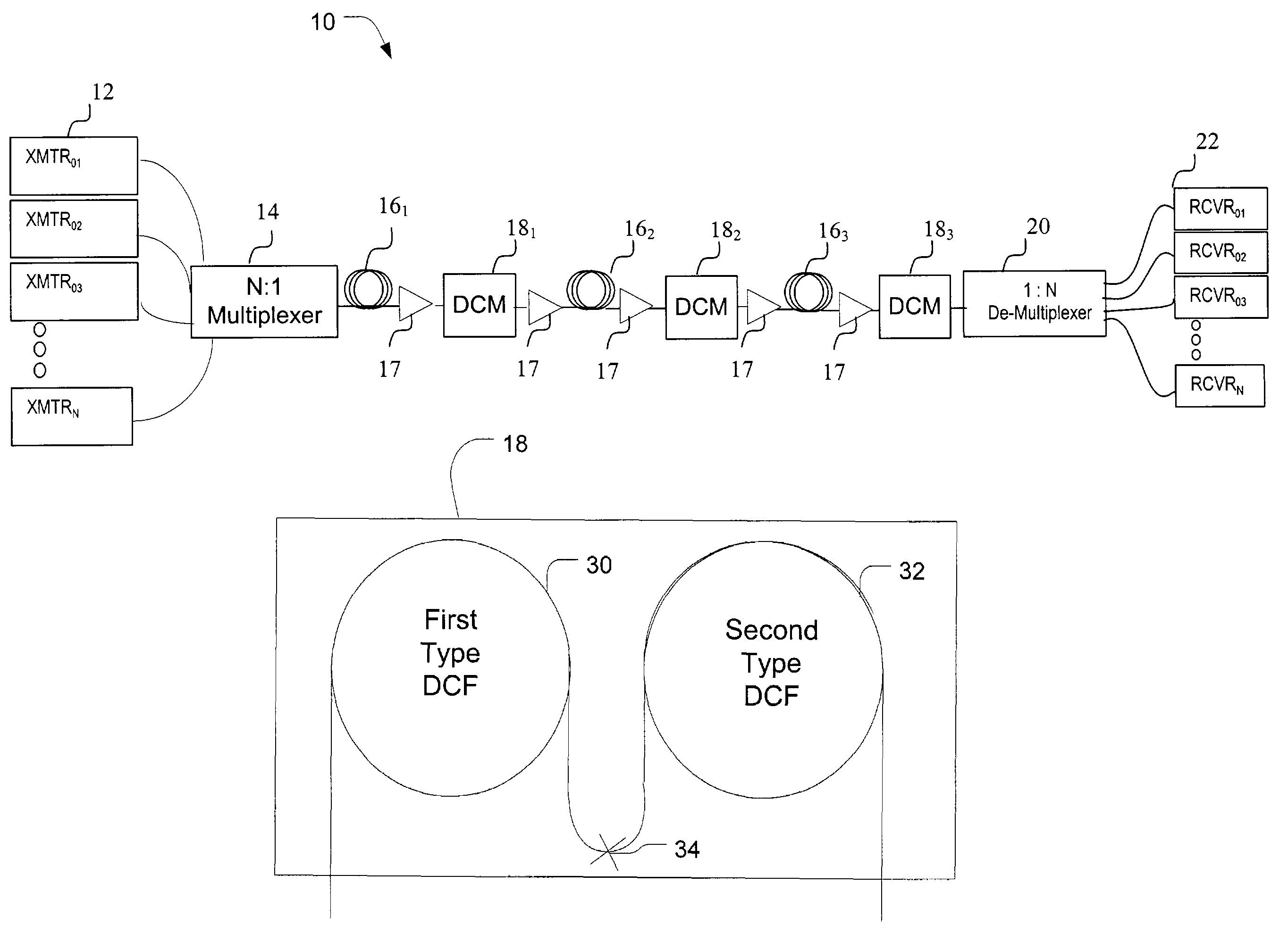
[0030]FIG. 4 depicts one span 10 of an optical communication network in an exemplary embodiment of the invention. The ...


PUM


Abstract

A method and system for compensating residual dispersion curvature in an optical communication network is disclosed. One embodiment employs two types of dispersion compensating fiber to reduce higher order terms in a residual dispersion profile. The two types of dispersion compensating fiber may be co-located in a dispersion compensation module positioned in each transmission fiber link. Alternatively, the two types of dispersion compensating fiber may be distributed across a span of the optical communication network.

Description

CROSS-REFERENCE TO RELATED APPLICATIONS[0001]This application is a continuation-in-part of both U.S. patent application Ser. No. 09 / 844,830 filed Apr. 27, 2001 now abandoned and U.S. patent application Ser. No. 09 / 844,826, filed Apr. 27, 2001, now abandoned the entire contents of which are incorporated herein by reference.BACKGROUND OF THE INVENTION[0002]1. Field of Invention[0003]This invention relates to a method and system for compensating for residual dispersion curvature.[0004]2. Description of Related Art[0005]Dispersion is a known phenomenon in optical communication networks that causes a broadening of input pulses traveling along the length of the fiber. One type of dispersion relevant to the invention is chromatic dispersion (also referred to as “material dispersion” or “intramodal dispersion”), caused by a differential delay of various wavelengths of light in a waveguide material.[0006]Dispersion has a limiting effect on the ability to transmit high data rates. When modula...

Claims


Application Information

Patent Timeline
IPC IPC(8): H04B10/00G02B6/34H04B10/18
CPCH04B10/2525G02B6/29376
Inventor SARDESAI, HARSHAD P.
Owner CIENA
Learn More