Golf club

a technology of golf clubs and balls, applied in golf clubs, sport apparatus, golf, etc., can solve the problems of reducing the repulsive force, the travel distance of the ball is less than the obtained, and so as to improve the hitting performance, the travel distance is not decreased, and the hitting performance is improved.

Active Publication Date: 2007-11-13
ENDO MFG COMPANY
View PDF11 Cites 364 Cited by
  • Summary
  • Abstract
  • Description
  • Claims
  • Application Information

AI Technical Summary

Benefits of technology

[0016]An object of the present invention is to provide a golf club such that the traveling distance is not decreased even if the ball is hit not only in the conventional sweet area, but also at a lower point.
[0017]Another object of the present invention is to provide a golf club such that when the golf club is addressed, the outer shape viewed by the player is not different from the conventional ones, and the hitting performance is improved with respect to the conventional one.
[0018]Yet another object of the present invention is to provide a golf club in which the hitting performance is improved and which can be manufactured by the processing method identical to that used for the manufacture of the conventional golf clubs.
[0019]The advantage of the golf club in accordance with the present invention is that when the golf club is addressed, the outer shape viewed by the player is not different from the conventional ones, and no psychological pressure is placed on the player.
[0020]Another advantage of the golf club in accordance with the present invention is that even if the ball flies at a low trajectory, the traveling distance is not different from that obtained when the ball is hit with the conventional sweet area.
[0031]a high-rigidity portion which is disposed in said metallic sole portion on the side of said back of said elastically deformable portion for increasing the rigidity of said disposed portion and for restoring elastic deformation with repulsion force close to explosiveness.

Problems solved by technology

For example, in a head (against) wind, golfers usually hit the ball in such a manner as to produce a low ball trajectory because if it is hit in the usual manner, the ball will have to fly against the wind, resulting in a failure to get the desired ball traveling distance.
This, however, results in a decrease of the repulsive force and the ball traveling distance becomes less than that obtained by striking on the sweet area.
However, the proposed methods have not yet satisfactorily solved the problems.
However, though the effect is obtained in specific locations, the repulsion effect cannot be reliably increased and maintained in the lower positions of the face.
Decreasing the head thickness is by itself limited because it decreases rigidity and reduces thickness.
If the thickness is too small, it may conversely degrade the repulsion.
Furthermore, a method wherein a weight portion is provided is effective in its own way but limited under the recent tendency for club head to increase in volume.
Thus, when a club head becomes large in size, the addition of a weight portion gives rise to a new problem that the mass of the head becomes large.
Further, all the aforementioned techniques of increasing the rigidity of the golf club are merely the techniques of increasing the rigidity of the entire body, and none of them has a double object of increasing the coefficient of restitution by decreasing rigidity of one part and increasing the traveling distance by increasing rigidity in the other part of the same golf club.
This may cause the swing rhythm to be destroyed.
Even if an epoch-making golf club is developed, it will take a long time for the new golf club to become established in actual practice.

Method used


Image

  • Golf club
  • Golf club
  • Golf club

Examples


first embodiment

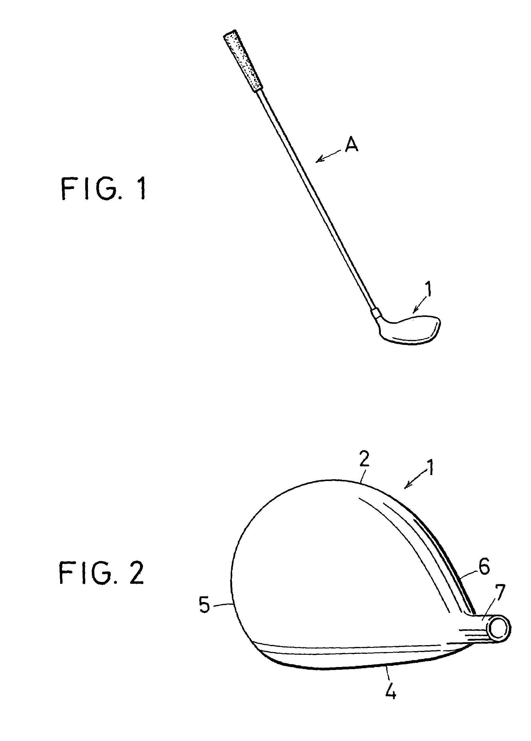
[0059]FIG. 1 is an external view showing the appearance of a golf club in accordance with the present invention; this figure shows a driver club head. The golf club in accordance with the present invention is primarily a metallic hollow golf club head. In the first embodiment, the explanation will be conducted with reference to a driver club head. A driver club head 1 of the first embodiment is supported on a shaft A. FIGS. 2 to 4 show an embodiment of the driver club head 1 in the metallic hollow golf club head of the first embodiment. FIG. 2 and figures thereafter show only the head, and other members such as shaft A are omitted therein.

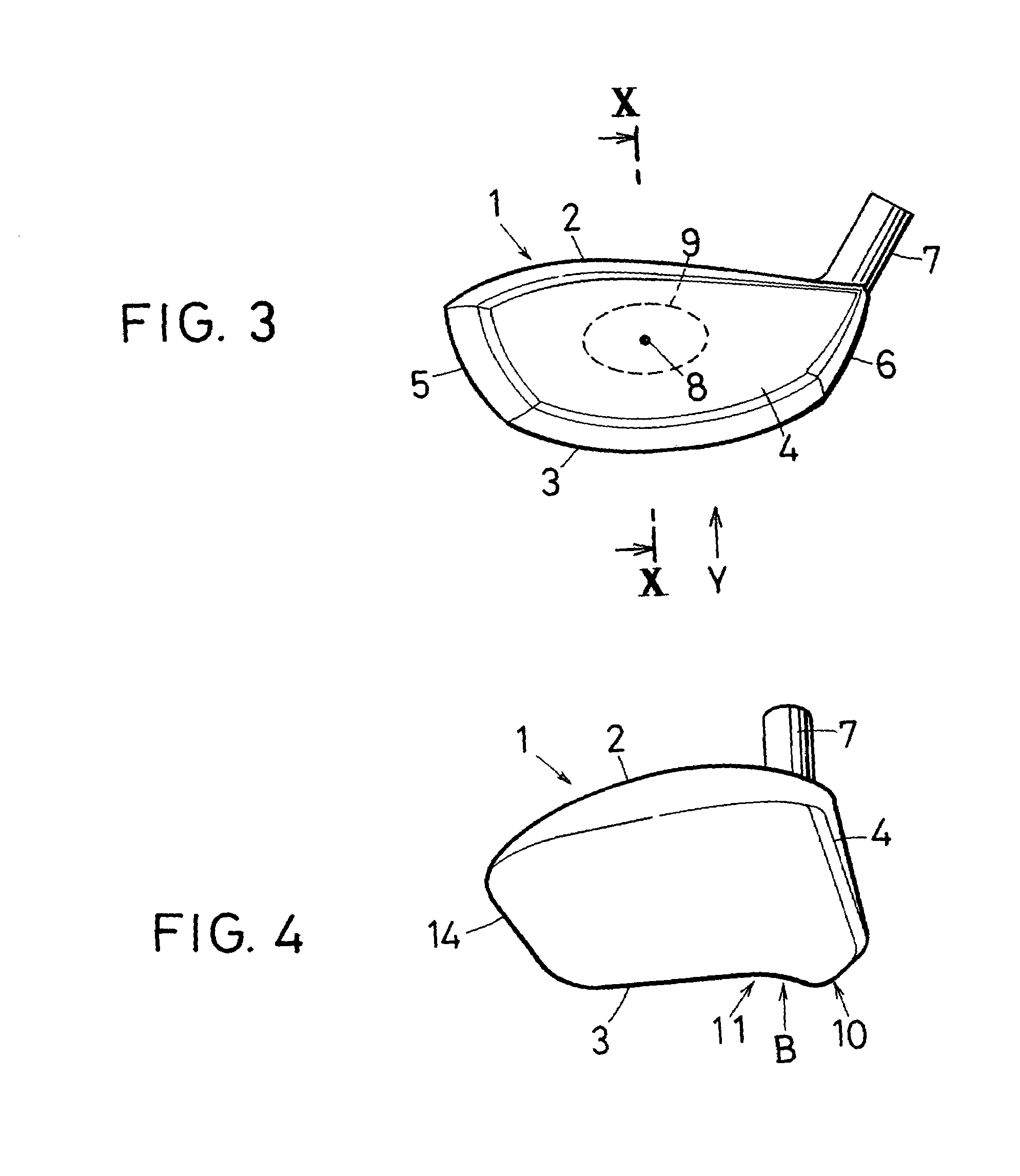
[0060]FIG. 2 is a plan view of the driver club head at the time the golf club is placed in an address state. FIG. 3 is a front view of the driver club head. FIG. 4 is a side view of the driver club head. As shown in the figures, the driver club head (hereinbelow referred to simply as “head”) 1 comprises a crown 2 corresponding to the top portion, a...

second embodiment

[0078]FIG. 8 illustrates the second embodiment in which the shape of the sole3 is different from that shown in FIG. 6. In the second embodiment, too, part of the face 4 has the configuration of the bent portion 4a identical to that in FIG. 6, projects to the sole 3 and is integrated therewith, thereby providing for increased rigidity. The difference between this configuration and that shown in FIG. 6 is that an elastically deformable groove (may be also called “recess”) 13 is provided. In this configuration, the thin plates acting as a high-rigidity body are also provided on the rear surface of the sole 3, similarly to the configuration shown in FIG. 7.

[0079]Formation of a projection and a recess in the sole 3 was explained below, but those projection and recess may also have an elastically deformable shape in the form of a plurality of waves. Further, the explanation above was conducted with respect to the case where the lower portion of the face 3 was bent, but the increased rigid...

third embodiment

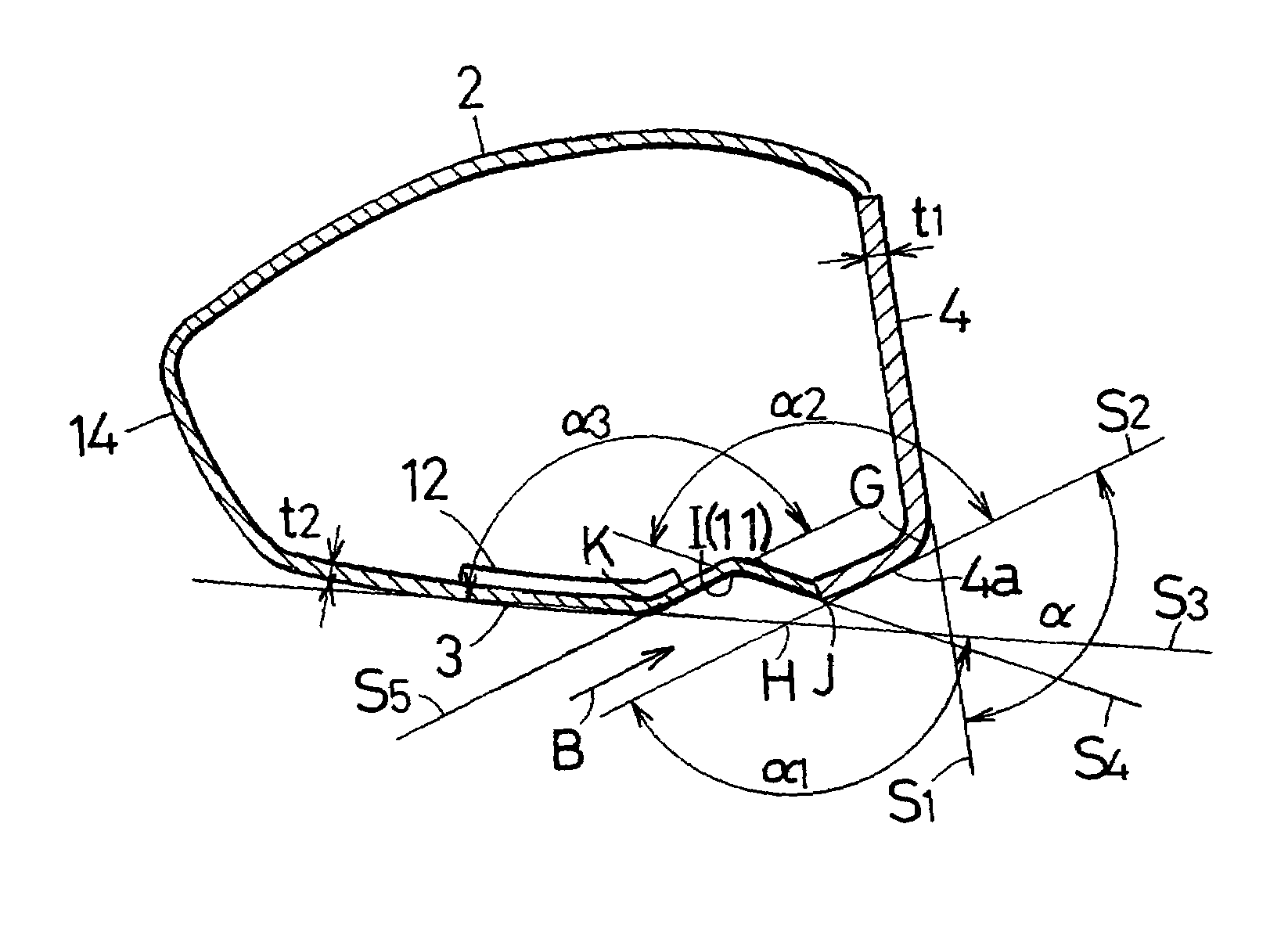
[0091]FIG. 11 shows a third embodiment of the present invention, which represents a modification example of the joint portion of the sole 3 from the bent portion 4a. In this embodiment, a bend 16 having a bend surface almost parallel to the hitting surface of the face 4 is formed in the joint portion. The sole 3 extending from the bend 16 to the back 14 is approximately flat and in a straight-line form in the sectional view of the figure. When an impact is received by the face 4, the bend 16 is deformed to a considerable extent.


PUM


Abstract

In a driver golf head (1) comprising a face (4) having a hitting surface, a sole (3) forming a lower portion, and a crown (5) forming an upper portion, the sole (3) is improved. The sole (3) in the position close to the face (4) was formed into an elastically deformable recess-projection shape, and part of the face (4) was formed into a projecting shape and integrated with the sole (3) to increase rigidity. Using a configuration with increased rigidity and decreased rigidity between the face (4) and sole to obtain an elastically deformable portion and providing a high-rigidity body (12) increased the repulsion force in the lower portion of the face and extended the traveling distance of the golf ball.

Description

BACKGROUND OF THE INVENTION[0001]1. Field of the Invention[0002]The present invention relates to golf clubs. More particularly, the present invention relates to a golf club having a club head sole modified to expand the sweet area downward of the face surface and to increase the traveling distance of golf balls.[0003]2. Description of the Related Art[0004]There are various golf clubs prepared for varying conditions of golf courses. For the middle- or long-range first shot, golf clubs called “drivers” are usually used in order to extend the ball traveling distance. Because the traveling distance affects the score directly, the position of the ball impact point on the golf club head is an important factor. The hitting surface of the golf club is called “face”. Under any conditions, the user usually strikes the ball on the face of the club head.[0005]At address, the center of gravity of a driver club head as projected on the club face is located above the center of the face as seen fro...

Claims


Application Information

Patent Timeline
Patent Type & Authority Patents(United States)
IPC IPC(8): A63B53/04
CPCA63B53/0466A63B2053/045A63B2053/0433A63B2053/0416A63B53/0416A63B53/0433A63B53/045
Inventor TSURUMAKI, MASAEIKOBAYASHI, KATSUHIROANDO, TAKAYUKI
Owner ENDO MFG COMPANY
Why Eureka
Try Eureka