Energy dissipating spring seat

a technology of energy dissipation spring and seat, which is applied in the direction of snap-action arrangement, protective switch operating/release mechanism, contact vibration/shock damping, etc., and can solve the problems of large number of components, wear and tear, and certain components are exposed to considerable for

Active Publication Date: 2007-11-13
EATON INTELLIGENT POWER LTD
View PDF12 Cites 33 Cited by
  • Summary
  • Abstract
  • Description
  • Claims
  • Application Information

AI Technical Summary

Problems solved by technology

While this configuration is effective, there are a substantial number of components required, each of which requires space to operate within and each of which are subject to wear and tear.
Further, certain components are exposed to considerable force, which enhances wear and tear, during operations wherein that particular component is not in use.
While the ram assembly requires few components, reduces the wear and tear on those components and may fit into a reduced space, the ram assembly, and more specifically the spring(s) of the ram assembly, cause an increase in stress on the supporting structure, i.e. the housing assembly or a frame assembly.

Method used


Image

  • Energy dissipating spring seat
  • Energy dissipating spring seat
  • Energy dissipating spring seat

Examples


Embodiment Construction

[0027]As used herein, “coupled” means a link between two or more elements, whether direct or indirect, so long as a link occurs.

[0028]As used herein, “directly coupled” means that two elements are directly in contact with each other.

[0029]As used herein, “fixedly coupled” or “fixed” means that two components so coupled move as one.

[0030]As used herein, “operatively engage” when used in relation to a component that is directly coupled to a cam means that a force is being applied by that component to the cam sufficient to cause the cam to rotate.

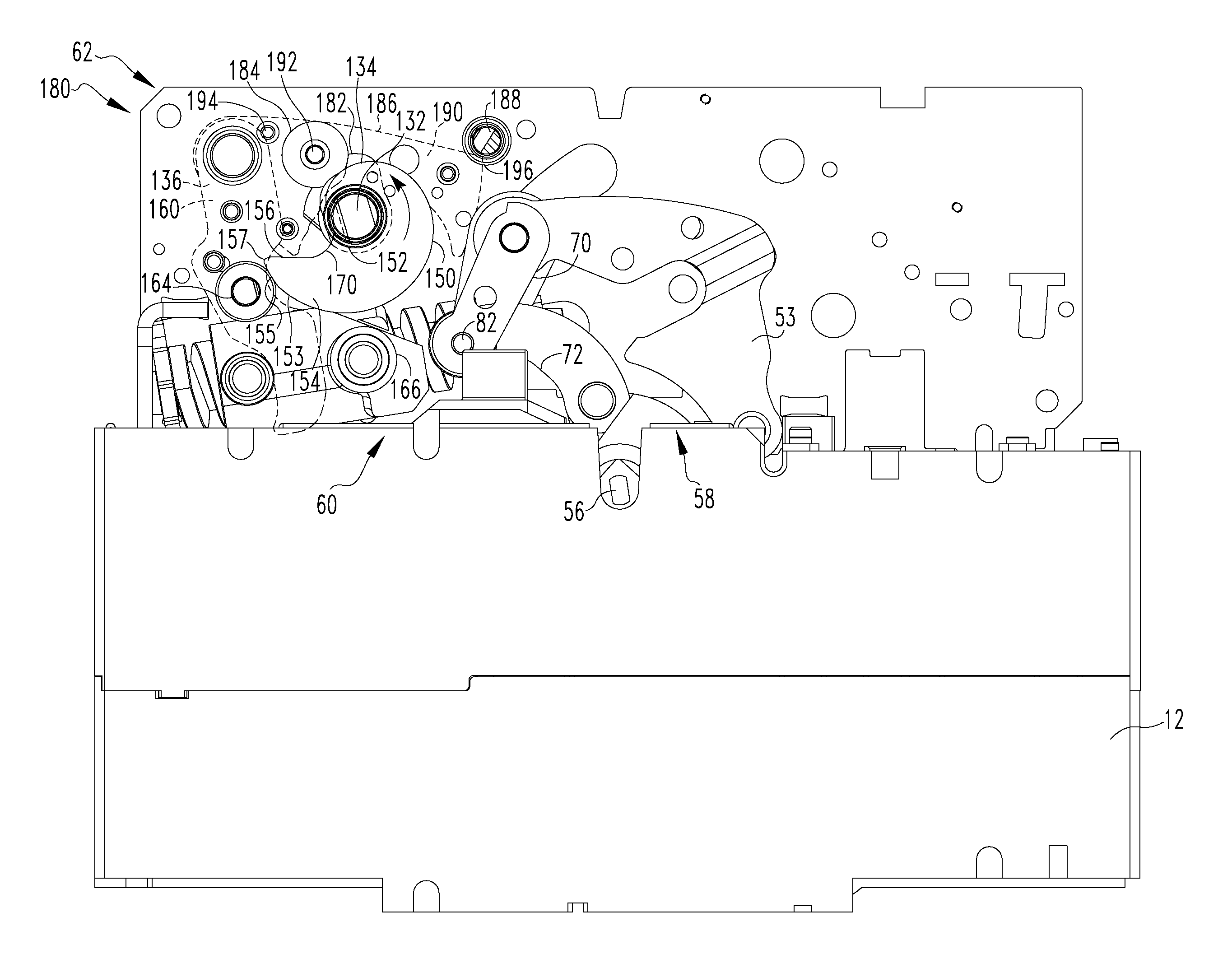
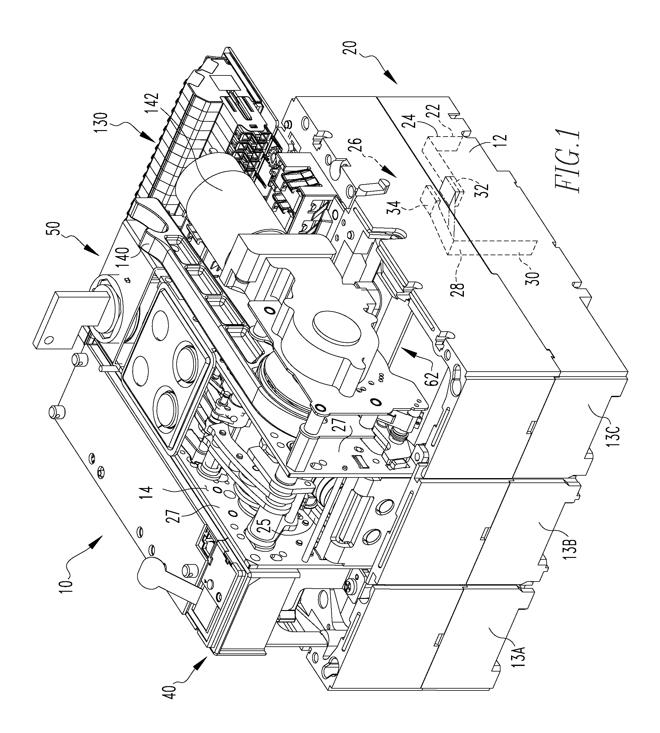
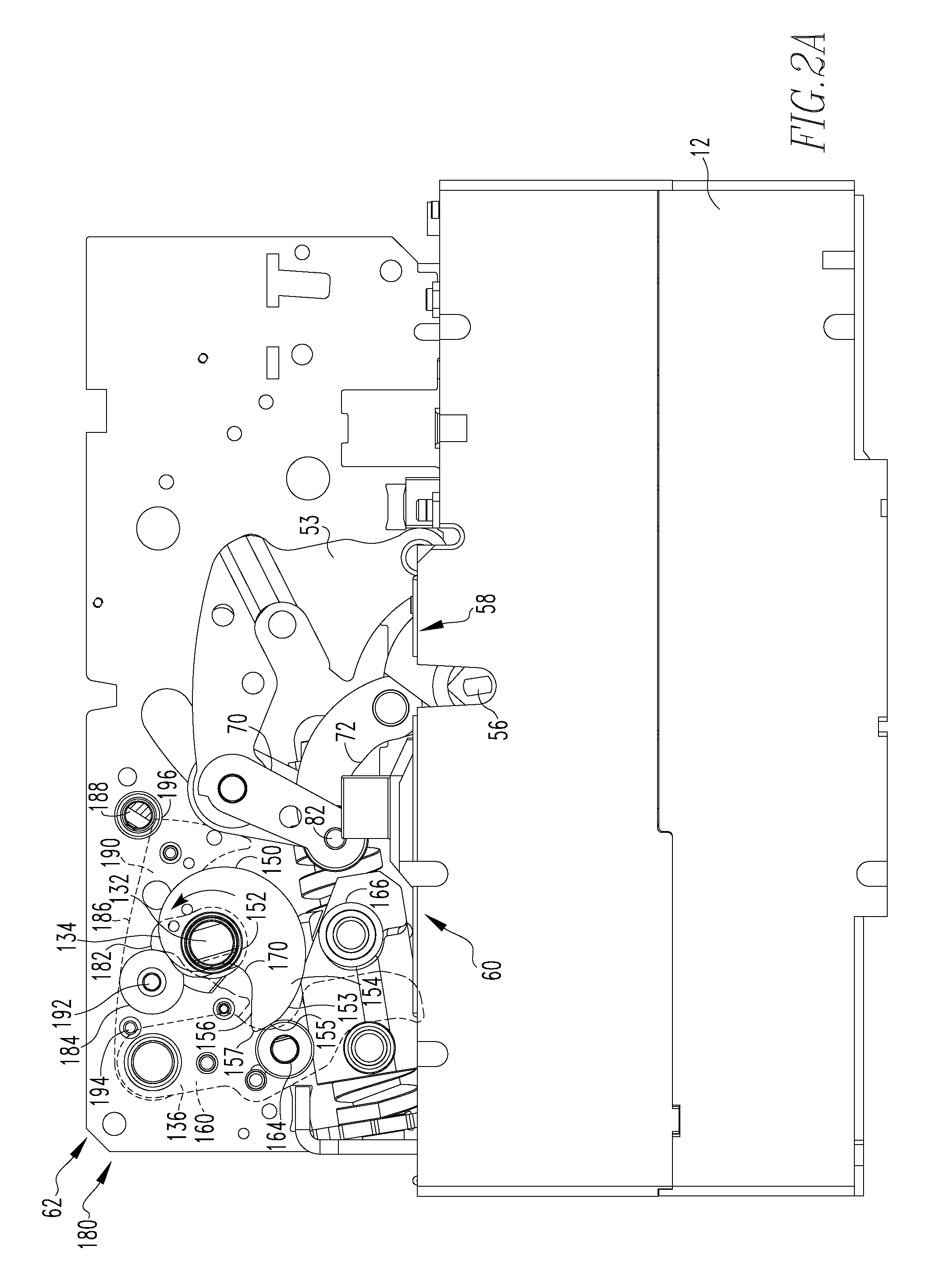
[0031]As shown in FIG. 1, an electrical switching apparatus 10 includes a housing assembly 12 defining an enclosed space 14. In FIG. 1, the front cover of the housing assembly 12 is not shown, but it is well known in the art. The electrical switching apparatus 10 further includes a conductor assembly 20 (shown schematically) having at least one line terminal 22, at least one line conductor 24, at least one pair of separable contacts 26, at lea...


PUM


Abstract

Within a closing assembly that utilizes a ram assembly having a spring driven ram body, an energy dissipating spring seat assembly is provided. The ram body is mounted on a guide assembly having at least one pin. The guide assembly also includes a base plate and a stop plate. A ram assembly spring is disposed between the ram body and the base plate and is structured to bias the ram body toward the stop plate. The spring seat assembly includes a spring seat bracket and a spring seat. The spring seat is, preferably, a generally flat, plate-like leaf spring that is disposed between the ram assembly springs and the base plate of the ram body. The spring seat is sufficiently rigid so as to not deflect fully under the force created by the compressed ram assembly springs, but not so rigid as to resist deflecting under the force created when the ram body impacts the stop plate.

Description

CROSS REFERENCE TO RELATED APPLICATION[0001]This application is related to commonly assigned, concurrently filed:[0002]U.S. patent application Ser. No. 11 / 693,198, filed Mar. 29, 2007, entitled “SPRING DRIVEN RAM FOR CLOSING AN ELECTRICAL SWITCHING APPARATUS”.BACKGROUND OF THE INVENTION[0003]1. Field of the Invention[0004]The present invention relates to a electrical switching apparatus operating mechanism and, more specifically to an energy dissipating spring seat coupled to a spring operated ram within the operating mechanism.[0005]2. Background Information[0006]An electrical switching apparatus, typically, includes a housing, at least one bus assembly having a pair of contacts, a trip device, and an operating mechanism. The housing assembly is structured to insulate and enclose the other components. The at least one pair of contacts include a fixed contact and a movable contact and typically include multiple pairs of fixed and movable contacts. Each contact is coupled to, and in ...

Claims


Application Information

Patent Timeline
Patent Type & Authority Patents(United States)
IPC IPC(8): H01H5/00
CPCH01H3/3015H01H3/60H01H71/66H01H71/50H01H2003/3068
Inventor GOTTSCHALK, ANDREW L.RAKUS, PAUL R.PARKS, DAVID A.
Owner EATON INTELLIGENT POWER LTD
Why Eureka
Try Eureka