Chuck

a chuck and chuck technology, applied in the direction of chucks, mechanical devices, manufacturing tools, etc., can solve the problems of inability to loosen the tool chuck, the force of the chuck cannot be unlimitedly increased,

Inactive Publication Date: 2007-11-20
SHANDONG WEIDA MASCH CO LTD
View PDF6 Cites 31 Cited by
  • Summary
  • Abstract
  • Description
  • Claims
  • Application Information

AI Technical Summary

Benefits of technology

[0003]The object of the present invention is to overcome the disadvantages in the prior art, and to provide a novel chuck for operations such as drilling and milling, which is reasonably configured, which can automatically exert force and clamp the tool shank and can refrain from exerting an excessive clamping force during operation, from which the tool shank can be conveniently manually removed, and meanwhile which can operate in both positive and reverse rotation states.BRIEF INTRODUCTION OF THE INVENTION
[0007]In the above state, the elastic locking detents of the detent lock ring are in engagement with and is locked with the reverse locking ratchet wheel, whereby the tool shank will not loosen in the event of reverse rotation operation, thereby overcoming the disadvantage that a common self-tightened chuck cannot operate in the reverse direction.

Problems solved by technology

Because the frictional force moment functions to limit the rotation of the movable ratchet wheel, the annular drive member and the nut relative to the body member, the increase of the clamping force of the jaws to the tool shank is to some extend limited so that the clamping force cannot unlimitedly increase, so that the tool shank cannot be loosened upon completion of the operation.

Method used


Image

  • Chuck
  • Chuck
  • Chuck

Examples


Embodiment Construction

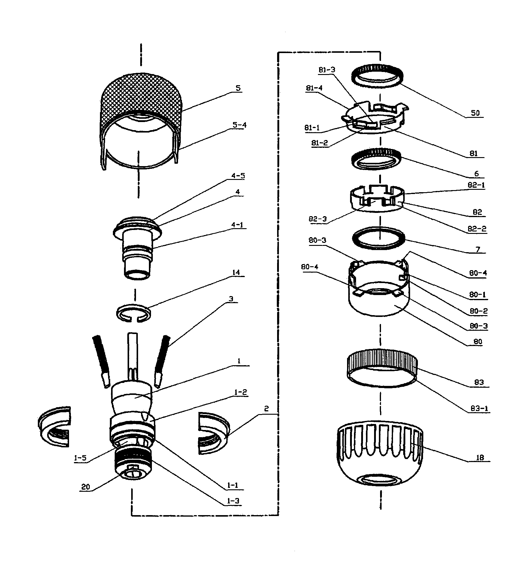
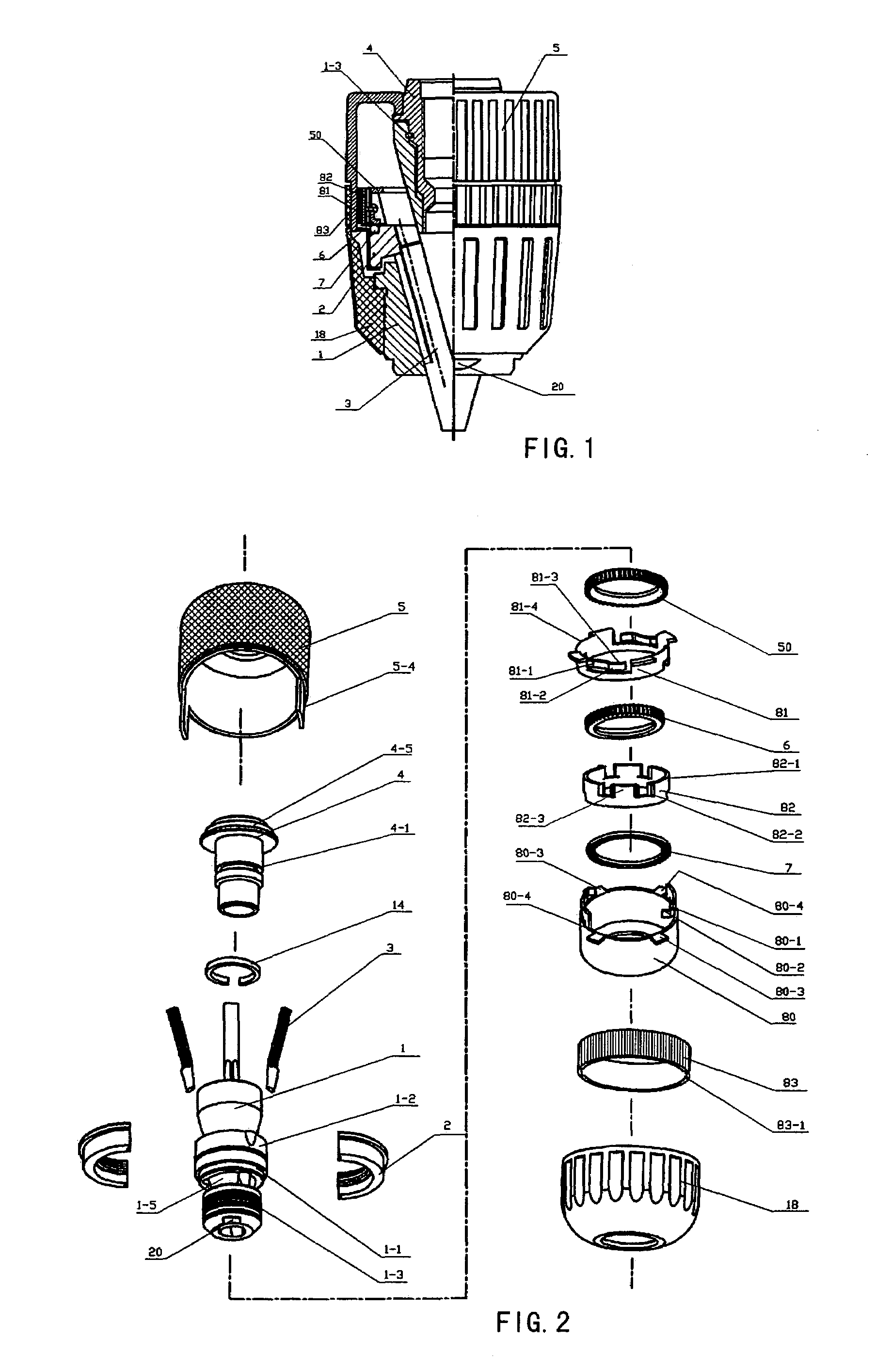
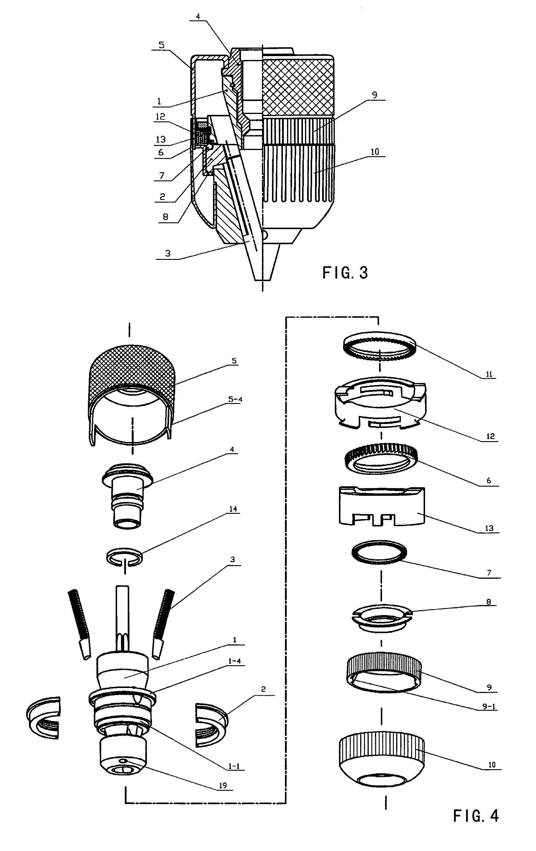
[0022]FIG. 1 is a structural schematic view of one embodiment of the present invention. FIG. 2 is an exploded schematic view of said embodiment. As shown in the figures, the present invention comprises a body member 1, a nut 2, jaws 3, a transmission connecting shaft 4, a drive sleeve 5, a movable ratchet wheel 6, a rolling member 7, a spring ring 14, a front sleeve 18, a reverse locking ratchet wheel 50, an annular drive member 80, a detent lock ring 81, a control ring 82, a control ring outer sleeve 83. Three jaws 3 are respectively received in three equally spaced angled bores of the body member 1, and the nut 2 engages with the jaws 3. The body member 1 is provided with a front end outer flange 1-3 having annular and longitudinal furrows, the outer flange being provided thereon with the front sleeve 18, the front end of the body member being provided with a multi-prismy structure 20. According to the present invention, the transmission connecting shaft 4 is mounted together with...


PUM


Abstract

The present invention relates to a self-tightened reverse locking chuck, comprising: a body member, a nut, jaws, a bearing, a drive sleeve, a front sleeve, an annular drive member, a movable ratchet wheel, a reverse locking ratchet wheel, a detent lock ring, a control ring and a control ring outer sleeve. The drive sleeve is positioned in a central hole in the rear end of the body member via a spring ring, drive keys on the drive sleeve can drive the annular drive member and the detent lock ring to rotate, in the chucked state, locked by the control ring. The chuck according to the present invention has the function of self-tightening, preventing the clamping force from being excessive, and of performing reverse rotation operation. The chuck is easy to assembly and disassembly, a tool shank clamped by the chuck will not be loosened due to vibration or shock, and the chuck is adapted for use in tools with various type of shank.

Description

TECHNICAL FIELD[0001]The present invention relates to a drill chucking device, and particularly, to a self-tightened reverse locking chuck.PRIOR ART[0002]As we all know, a drill chuck in the prior art generally comprises such parts as a body member, jaws, a nut, a nut jacket, a rolling member, an outer sleeve and a locking device. Three jaws are respectively received in three equally spaced angled bores of the body member, the nut is disposed in a nut groove of the body member, the threads of the nut engage with those on the jaws to form a thread transmission mechanism, the nut jacket is connected, with interference, to the nut, the exterior of the nut jacket is provided with the outer sleeve, the inner wall of the outer sleeve is provided with keys, the nut jacket or the nut are provided thereon with key slots, and the outer sleeve is connected to the nut jacket or the nut via the keys. In mounting and use, the body member is directly connected to a transmission shaft of a power-ge...

Claims


Application Information

Patent Timeline
Patent Type & Authority Patents(United States)
IPC IPC(8): B23B31/12
CPCB23B31/123B23B31/1238B23B2231/38Y10S279/902Y10T279/3493Y10T279/17623Y10T279/17632Y10T279/32Y10T279/17615Y10T279/20
Inventor YANG, GUIMOTAN, XINGDA
Owner SHANDONG WEIDA MASCH CO LTD
Why Eureka
Try Eureka