Carrying cases with pop-out compartments

Inactive Publication Date: 2005-01-04
EZM
View PDF31 Cites 43 Cited by
  • Summary
  • Abstract
  • Description
  • Claims
  • Application Information

AI Technical Summary

Benefits of technology

Moreover, it is an object of the present invention to protect an object disposed in a pop-out compartment of a carrying case so that, when the pop-out compartment is disposed in the interior of the carrying case, the object is protected from contact with other objects in the interior.
Some of the advantages of the present invention are that one or more objects may be stabilized and held in place and/or protected on the external panel when the one or more objects are disposed in the interior as well as when the external panel is pivoted to move the one or more objects through the opening in the external wall; the one or more objects may be removed from and/or placed in the interior via the external panel without disturbing other contents of the carrying case; the one or more objects disposed in the pop-out compartment defined by the external panel may be frequently accessed objects such that removal of one or more frequently accessed objects from and placement of one or more frequently accessed objects in the interior is made more convenient; only a small amount of exterior space is needed to accommodate movement of the external panel away from the external wall; the one or more objects can be removed from or placed in the interior via the external panel with the carrying case disposed in various orientations; the one or more objects are removably secured on the external panel in a manner facilitating their removal from and placement in the pop-out compartment; various structure can be used on the external panel to removably secure, stabilize and/or protect the one or more objects; the one or more objects in the pop-out compartment are isolated or separated from other contents of the carrying case during retraction and withdrawal of the pop-out compartment; the external panel may be designed with a self-closing effect to retract the pop-out compartment and close the opening in the external wall when the external panel is not moved outwardly away from t

Problems solved by technology

It is often inconvenient for a user to remove a frequently accessed object from and/or to place a frequently accessed object in an interior compartment of conventional carrying cases via the compartment opening.
For example, the closure of the compartment opening may be relatively difficult or inconvenient to operate; a frequently accessed object in the interior compartment may be difficult to access via the compartment opening due to its location in the interior compartment and/or the presence of other objects in the interior compartment; the carrying case may assume a considerably larger profile in an open position with the compartment opening open than in a closed position with the compartment opening closed so as to require considerable surrounding space to access the interior compartment via the compartment opening; and/or the carrying case may need to be supported or placed on a support surface in the open position.
The external pockets are ordinarily not in communication with an interior compartment of the carrying cases such that frequently accessed objects in the external pockets cannot also be removed through the interior compartment when the corresponding compartment opening is open.
In addition, frequently accessed objects may inadvertently fall out of the external pockets and be lost and/or damaged, especially when the carrying cases are dropped, tipped over, toppled or turned upside down.
The pockets afford little structural protection for the objects against damage due to shocks and other impacts, even while the external location of the pockets places the objects therein at increased risk of damage from impacts.
A further disadvantage associated with carrying cases having external pockets is that the objects within the pockets are usually at least partially visible from exteriorly of the carrying cases.
Where the objects are perceived to be valuable, as may be the case for many electronic devices, the objects are at increased risk of theft, especially since the objects are

Method used


Image

  • Carrying cases with pop-out compartments
  • Carrying cases with pop-out compartments
  • Carrying cases with pop-out compartments

Examples


Embodiment Construction

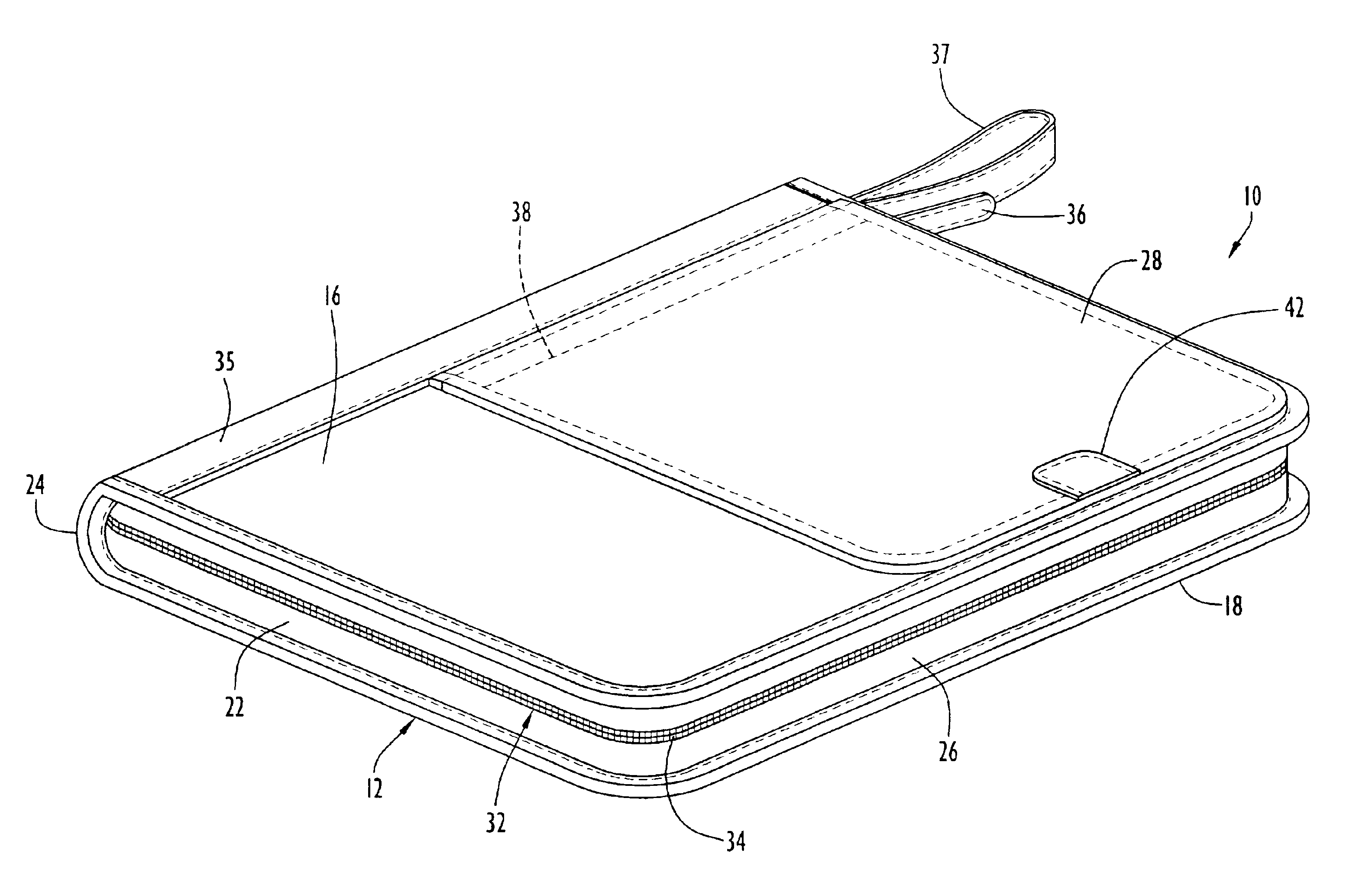
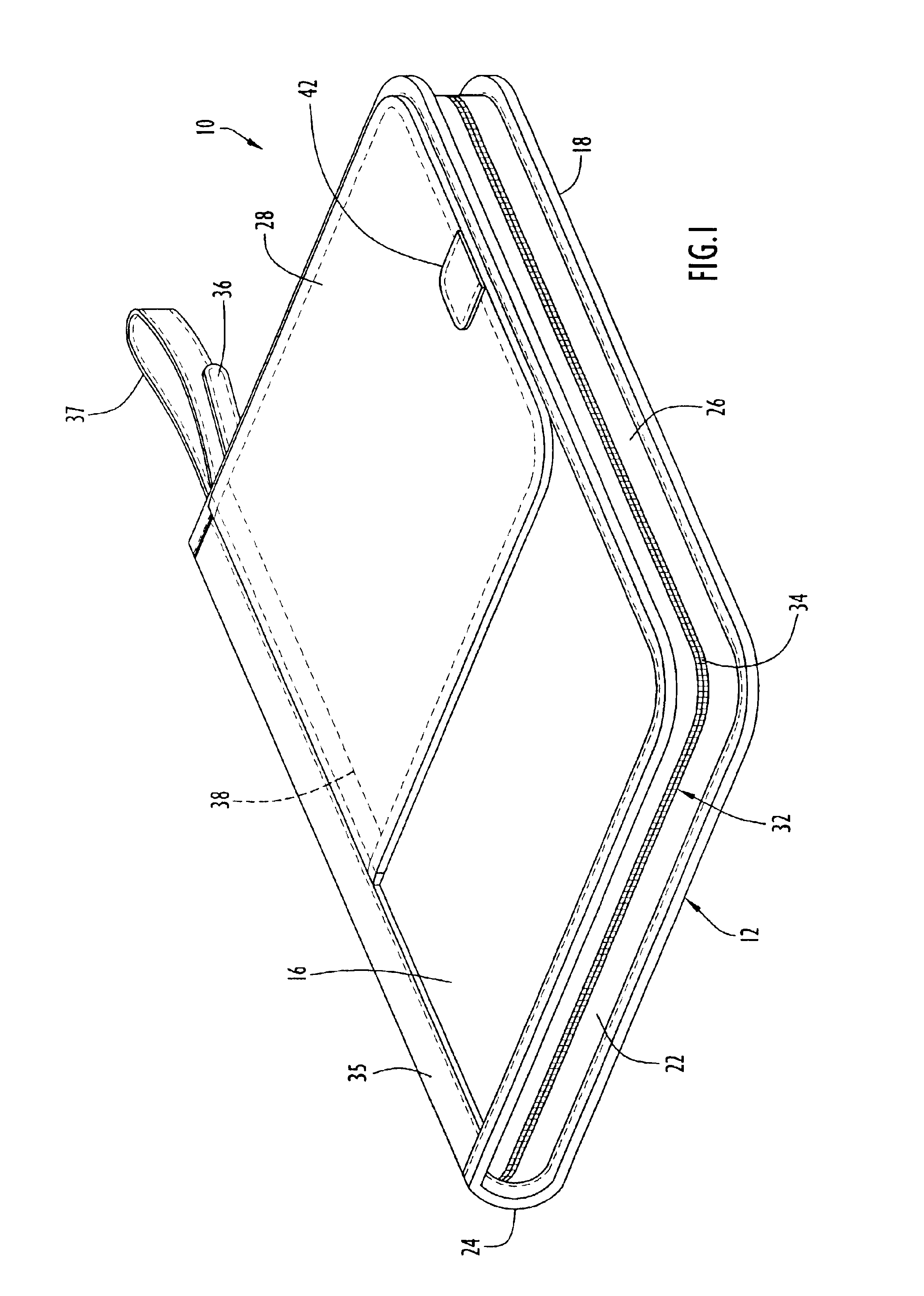
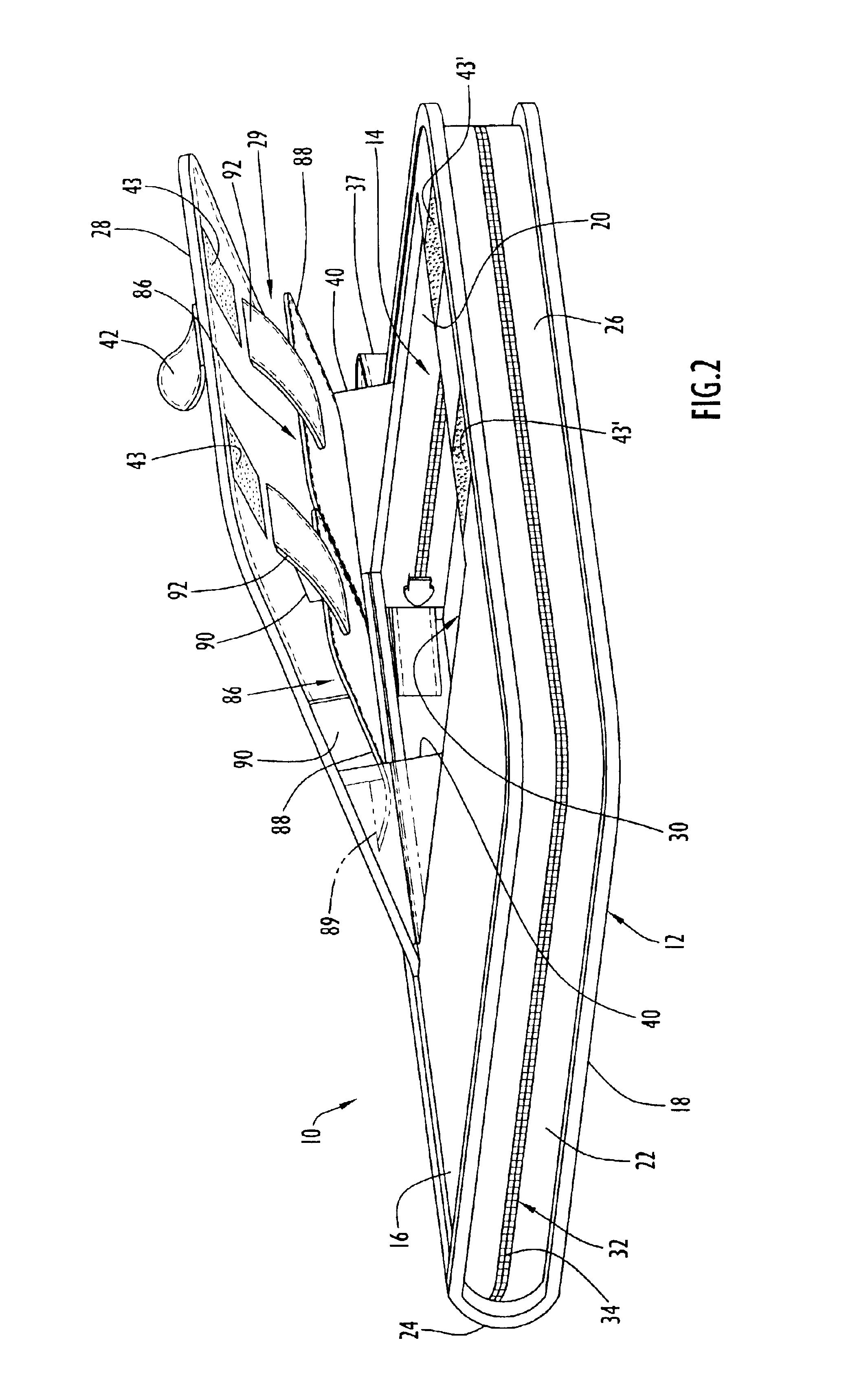
A carrying case 10 according to the present invention is illustrated in FIGS. 1-4 and comprises a body or enclosure 12 enclosing an interior defining an interior compartment 14. The body 12 can have various external configurations and may be designed, for example, as a notebook, a portfolio, an attache case, a briefcase, a duffle bag, or a suitcase. The body 12 for carrying case 10 is similar to a notebook or portfolio and is defined by a plurality of external walls including a front wall 16, a back wall 18, a top wall 20, a bottom wall 22, a left side wall 24, a right side wall 26, and an external panel 28 on front wall 16 defining a pop-out compartment 29. It should be appreciated that the terms “front”, “back”, “top”, “bottom”, “left” and “right” are all relative terms applicable to the external walls 16-26, respectively, when the carrying case 10 is viewed and oriented as shown in FIGS. 1-4 but that each of the latter terms can apply to any of the external walls 16-26 depending ...


PUM


Abstract

A carrying case comprises an enclosure including a plurality of external walls and an external panel disposed over a window in one of the external walls communicating with an interior compartment. The enclosure has a selectively openable, selectively closable compartment opening providing access into the interior compartment when the opening is open and which prevents access into the interior compartment when the opening is closed. The panel defines a pop-out compartment adapted to carry an object and has a retracted position wherein the pop-out compartment is disposed within the interior compartment for removal of the object from the enclosure through the compartment opening. The panel is pivotable from the retracted position to an extended position wherein the pop-out compartment is withdrawn from the interior compartment for removal of the object from the enclosure via the pop-out compartment independent of the compartment opening.

Description

BACKGROUND OF THE INVENTION1. Field of the InventionThe present invention relates generally to carrying cases enclosing an interior compartment accessible via a selectively openable and selectively closable compartment opening and, more particularly, to a carrying case in which an object is removable from and placeable in the interior compartment with the compartment opening closed while also being removable from and placeable in the interior compartment via the compartment opening.2. Brief Description of the Related ArtCarrying cases have become very popular for use in conveniently storing and transporting various objects such as electronic devices, documents, and other personal and business effects. Conventional carrying cases generally enclose an interior defining an interior compartment accessible via a compartment opening that is selectively opened and closed via a closure of the opening. The interior compartment is adapted to hold various objects, sometimes in an organized or ...

Claims


Application Information

Patent Timeline
IPC IPC(8): A45C3/00A45C3/02A45C5/00A45C5/06A45C13/00A45C13/02
CPCA45C3/02A45C5/06A45C13/345A45C13/02
Inventor HOLLINGSWORTH, W. DALE
Owner EZM
Why Eureka
Try Eureka