
Covers for distribution lines and insulators

a technology of distribution lines and insulators, applied in the direction of overhead lines/cables, maintaining distance between parallel conductors, substations, etc., can solve the problems of power outage or other problems of the power distribution system, birds or other animals may land or climb on the lines,

Active Publication Date: 2007-11-20
TYCO ELECTRONICS LOGISTICS AG (CH)
View PDF48 Cites 257 Cited by
  • Summary
  • Abstract
  • Description
  • Claims
  • Application Information

AI Technical Summary

Benefits of technology

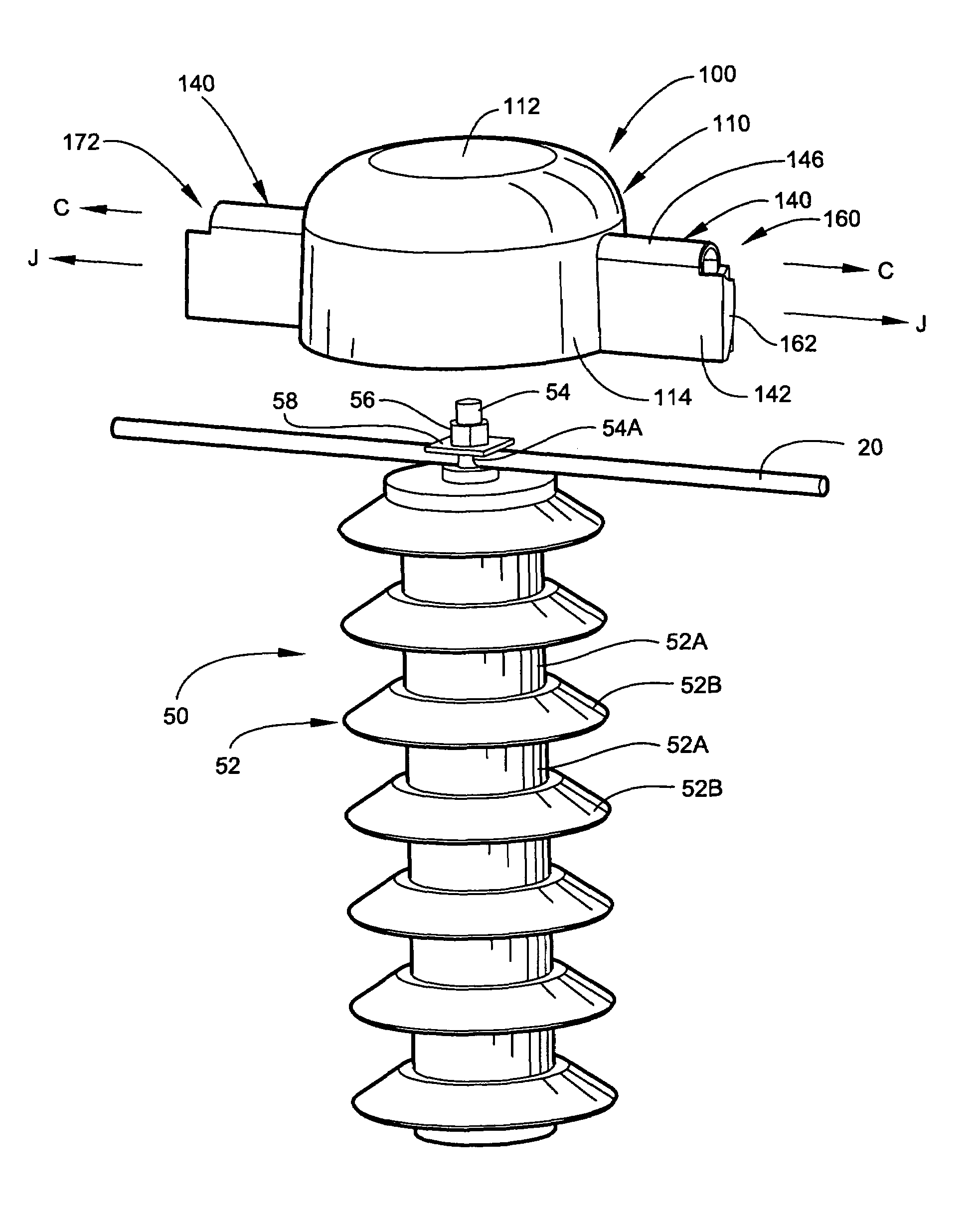
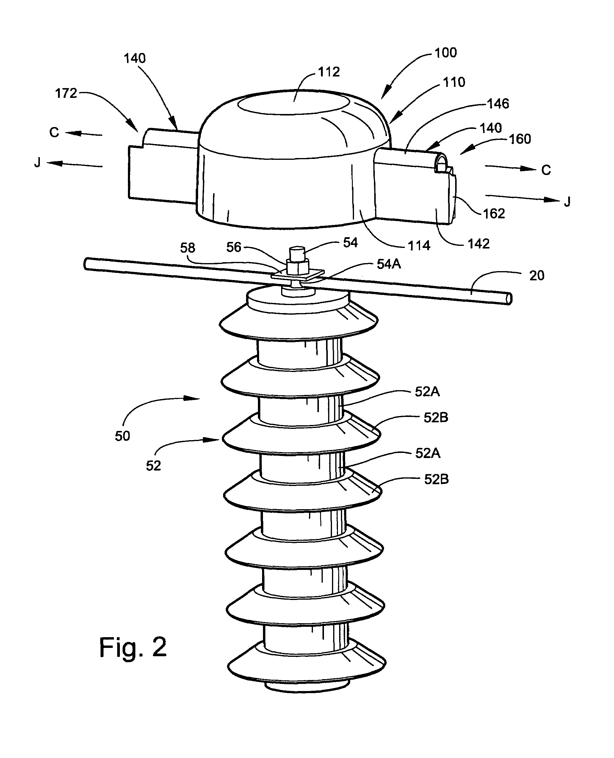
[0003]According to embodiments of the present invention, a cover for a distribution line conductor includes a cover body defining a channel extending along a lengthwise axis and adapted to receive the conductor. A unitarily formed attachment structure adjoins the cover body. The attachment structure includes first and second jaws positioned adjacent the channel. The first and second jaws are positioned at different locations along a jaw axis parallel to the lengthwise axis and, in a closed position, overlap one another across the jaw axis. The first and second jaws are relatively deflectable from the closed position to an open position to permit passage of the conductor therebetween and into the channel and the first and second jaws can thereafter return toward the closed position to secure the conductor in the channel.

Problems solved by technology

One problem with such lines, particularly with power distribution lines that transmit electrical power at high voltages, is that birds or other animals may land or climb onto the lines.
Such contact of distribution lines by animals, particularly adjacent the support structure, may cause a short or electrical flash-over allowing current flow through the animal, which may cause a power outage or other problem with the power distribution system.

Method used


Image

  • Covers for distribution lines and insulators
  • Covers for distribution lines and insulators
  • Covers for distribution lines and insulators

Examples


Embodiment Construction

[0019]The present invention now will be described more fully hereinafter with reference to the accompanying drawings, in which illustrative embodiments of the invention are shown. In the drawings, the relative sizes of regions or features may be exaggerated for clarity. This invention may, however, be embodied in many different forms and should not be construed as limited to the embodiments set forth herein; rather, these embodiments are provided so that this disclosure will be thorough and complete, and will fully convey the scope of the invention to those skilled in the art.

[0020]It will be understood that when an element is referred to as being “coupled” or “connected” to another element, it can be directly coupled or connected to the other element or intervening elements may also be present. In contrast, when an element is referred to as being “directly coupled” or “directly connected” to another element, there are no intervening elements present. Like numbers refer to like elem...


PUM


Abstract

A cover for a distribution line conductor includes a cover body defining a channel extending along a lengthwise axis and adapted to receive the conductor. A unitarily formed attachment structure adjoins the cover body. The attachment structure includes first and second jaws positioned adjacent the channel. The first and second jaws are positioned at different locations along a jaw axis parallel to the lengthwise axis and, in a closed position, overlap one another across the jaw axis. The first and second jaws are relatively deflectable from the closed position to an open position to permit passage of the conductor therebetween and into the channel and the first and second jaws can thereafter return toward the closed position to secure the conductor in the channel.

Description

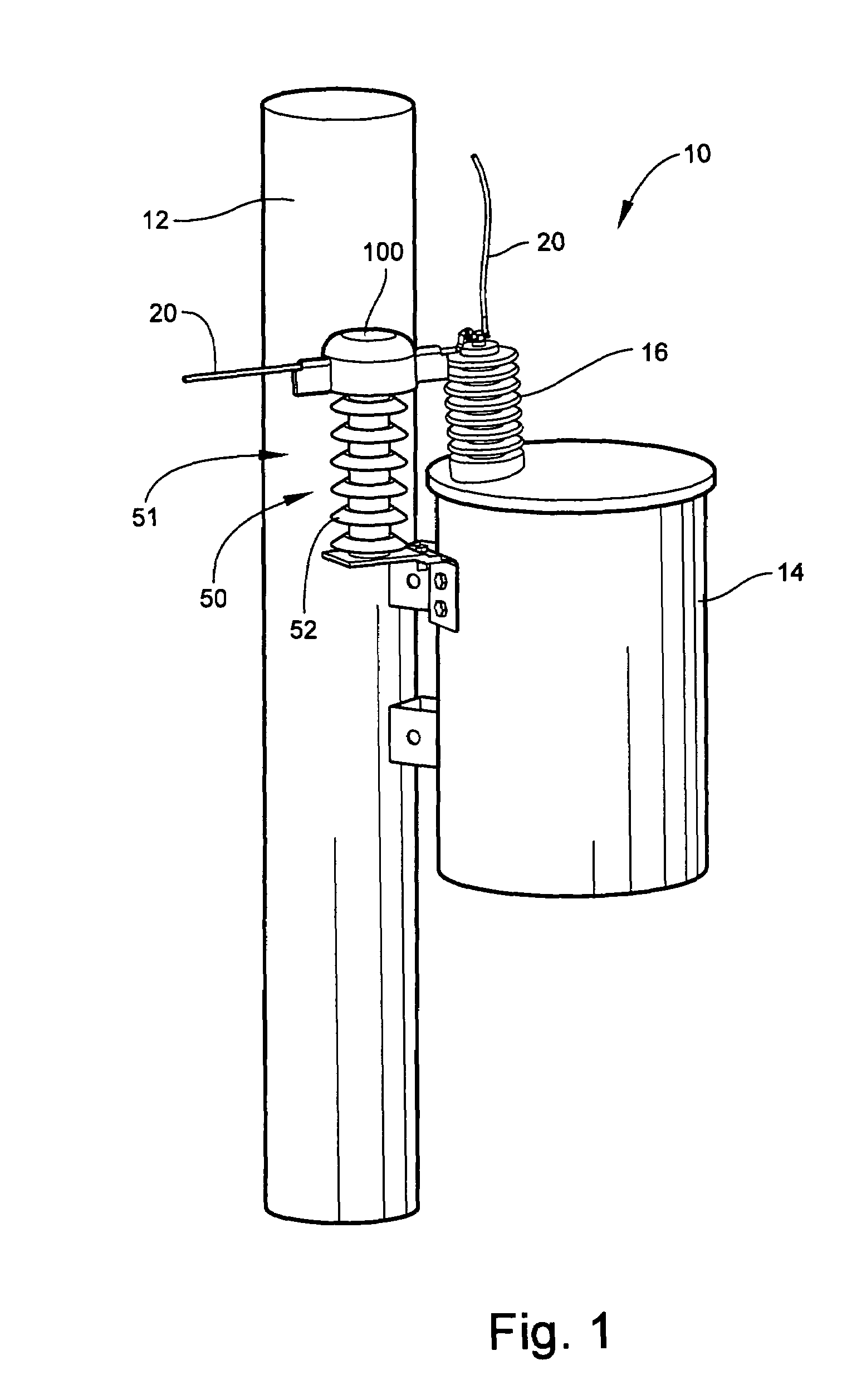
FIELD OF THE INVENTION[0001]The present invention relates to protective covers and, more particularly, to protective covers for distribution lines and insulators, such as power distribution lines and associated insulators.BACKGROUND OF THE INVENTION[0002]Support structures, such as utility poles, are often used to suspend electrical lines, such as power distribution lines, above the ground. These support structures are generally located outdoors and may be of a variety of different configurations to suspend one or more lines. One problem with such lines, particularly with power distribution lines that transmit electrical power at high voltages, is that birds or other animals may land or climb onto the lines. Such contact of distribution lines by animals, particularly adjacent the support structure, may cause a short or electrical flash-over allowing current flow through the animal, which may cause a power outage or other problem with the power distribution system.SUMMARY OF THE INVE...

Claims


Application Information

Patent Timeline
Patent Type & Authority Patents(United States)
IPC IPC(8): H02G7/16
CPCH01B17/00
Inventor HILLER, LAURA JACKSONPUIGCERVER, LUIS O.GLEMBOCKI, ROBERT PAULBLUE, KENTON A.
Owner TYCO ELECTRONICS LOGISTICS AG (CH)
Learn More