
Photoluminescent wall marker and method of making

a technology of photoluminescent wall and marker, which is applied in the field of photoluminescent wall markers, can solve the problems of inconvenient storage and transportation, and inability to meet the needs of use, etc., and achieve the effect of efficient storage and transportation

Inactive Publication Date: 2007-11-20
BRADY WORLDWIDE INC
View PDF11 Cites 2 Cited by
  • Summary
  • Abstract
  • Description
  • Claims
  • Application Information

AI Technical Summary

Benefits of technology

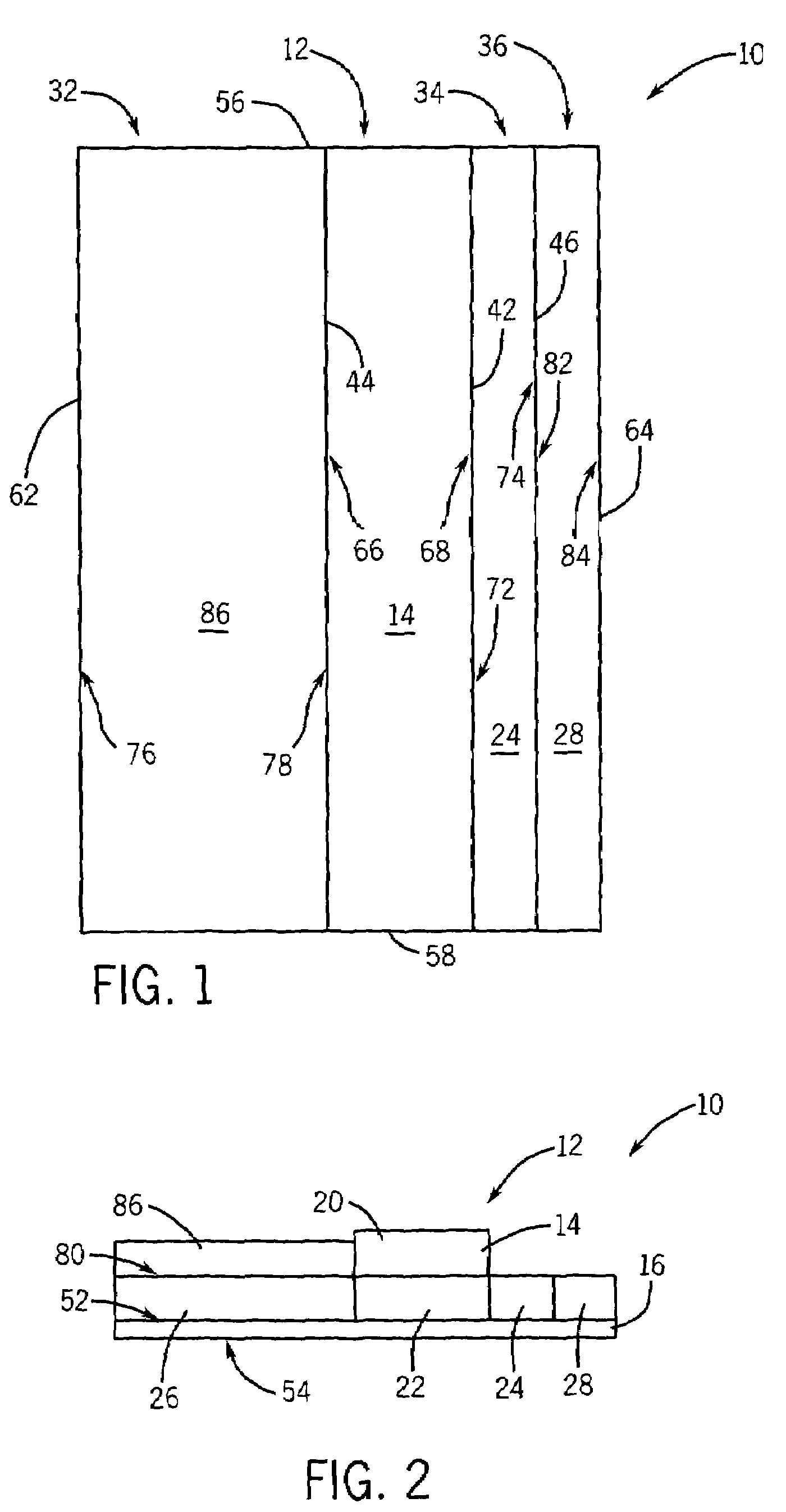
[0012]The present invention provides a photoluminescent wall marker including upwardly facing photoluminescent material and can be stored in roll form. In one embodiment, the wall marker includes an elongated base having an upper edge and a lower edge. The lower edge of the base is integral with an upper edge of a photoluminescent panel. The upper edge of the photoluminescent panel is integral with the base lower edge and defined by a fold line extending longitudinally between the base and the photoluminescent panel. The base and photoluminescent panel are flexible in a transverse direction allowing the wall marker to be stored in roll form in an unassembled configuration.
[0013]A general objective of the present invention is to provide an effective wall marker that can be efficiently stored and transported. This objective is accomplished by providing a wall marker that can be stored in roll form and dispensed with an angled photoluminescent panel.

Problems solved by technology

Other pigments, such as zinc sulfide can also be used, however the performance isn't quite as long lasting.
When the UV light source is removed, the afterglow of visible light discharge continues for some time, although it does decay eventually.
Without sufficient UV light to charge the sign, the afterglow is limited.
Sometimes the egress marking cannot be applied to the floor, either due to a difficult to bond surface, difficulty in cleaning or otherwise preparing the surface for bonding, or other obstacles.
This angle can diminish the effectiveness of the marking and slow recognition by the viewer in a black-out, emergency situation.
The disadvantage of the current angled mounts is that they must be made in rigid lengths.
Even eight foot lengths present a challenge for convenient handling, especially when being transported up emergency exits on multi-story buildings.
Flat tapes and flat mounts for tapes and markings can be provided and dispensed from convenient rolls in much greater lengths, but do not supply the angled display feature.

Method used


Image

  • Photoluminescent wall marker and method of making
  • Photoluminescent wall marker and method of making
  • Photoluminescent wall marker and method of making

Examples


Embodiment Construction

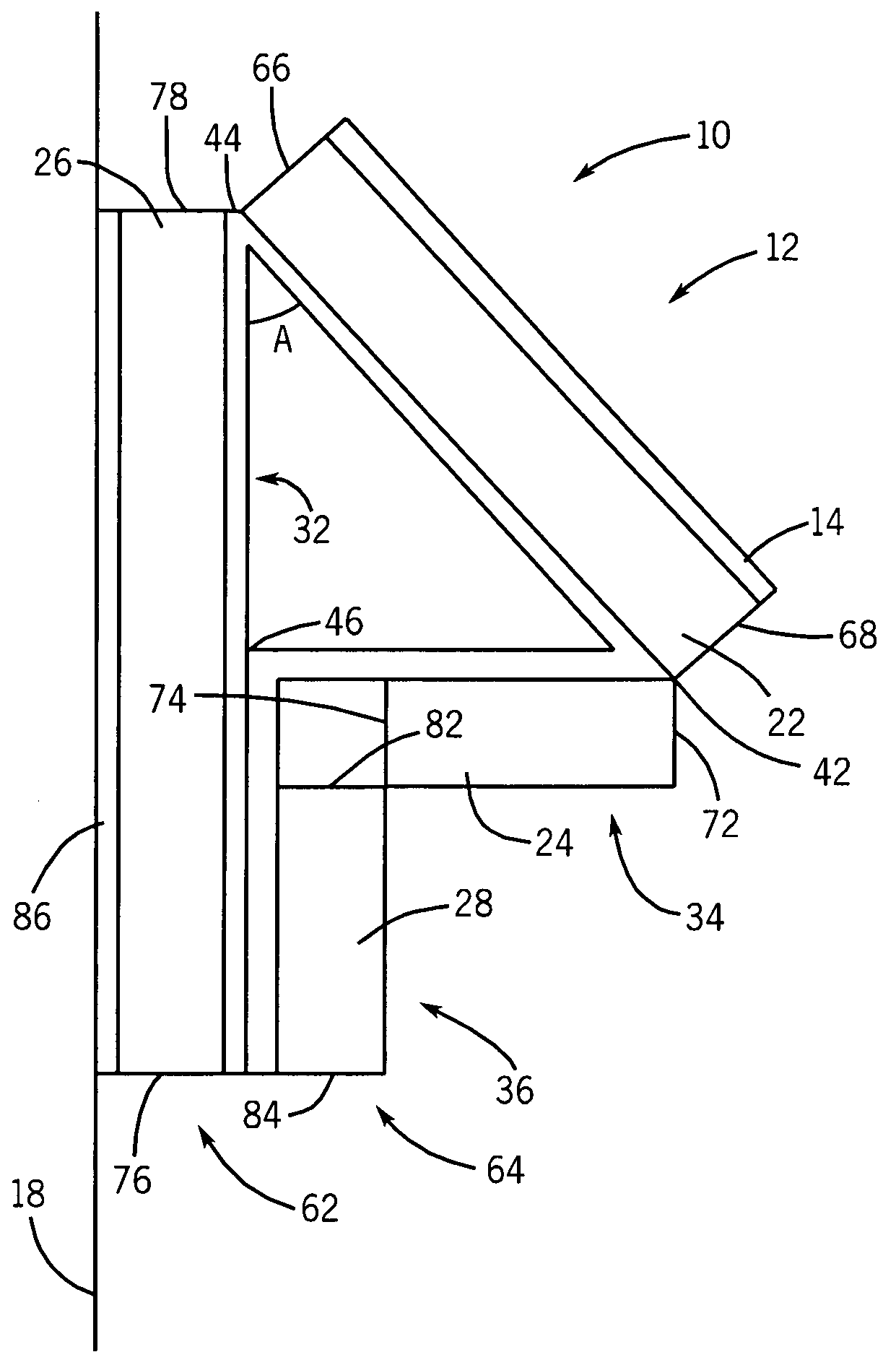
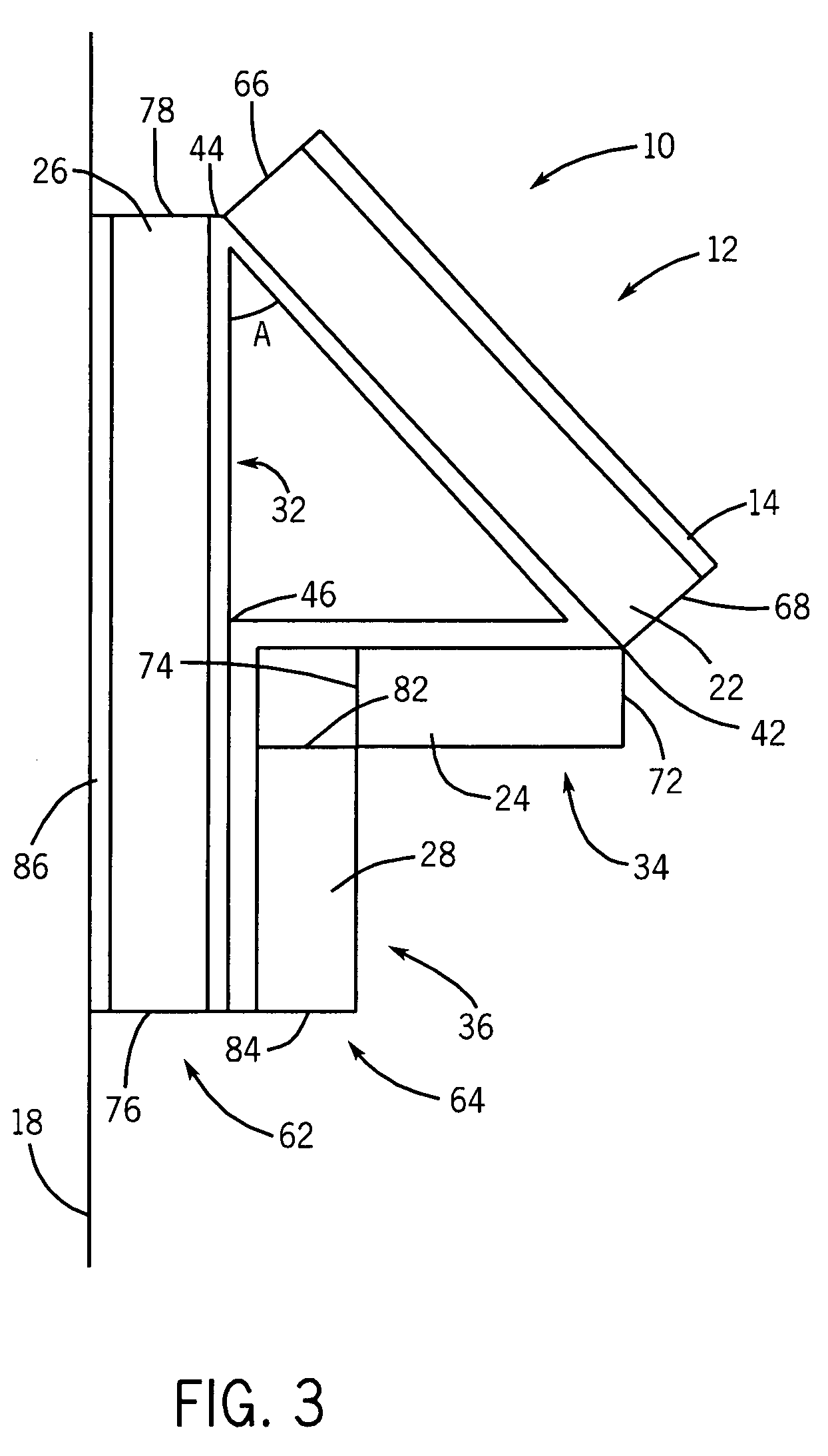
[0020]A preferred embodiment of a photoluminescent wall marker 10 shown in FIGS. 1-3 can be stored and transported in an unassembled configuration (FIGS. 1 and 2) in roll form and dispensed in an elongated strip that is folded to form a three-dimensional structure in an assembled configuration (FIG. 3) for affixing to a wall 18. The three-dimensional structure includes an upwardly facing photoluminescent panel 12 having a photoluminescent material 14 charged by ambient light.

[0021]The wall marker 10 includes an elongated substrate 16 on which strips 20, 22, 24, 26, 28 of stiffening material and the photoluminescent material 14 are affixed defining a base 32, the photoluminescent panel 12, a support segment 34, and an anchor 36. Preferably, the base 32, photoluminescent panel 12, support segment 34, and anchor 36 are separated from each other by fold lines 42, 44, 46 extending substantially the entire length, i.e. in a longitudinal direction, of the elongated substrate 16. Advantageo...


PUM

PropertyMeasurementUnit
lengthsaaaaaaaaaa
thicknessaaaaaaaaaa
widthaaaaaaaaaa

Abstract

A photoluminescent wall marker includes an elongated base having an upper edge and a lower edge. The lower edge of the base is integral with an upper edge of a photoluminescent panel. The upper edge of the photoluminescent panel is integral with the base lower edge and defined by a fold line extending longitudinally between the base and the photoluminescent panel. The base and photoluminescent panel are flexible in a transverse direction allowing the wall marker to be stored in roll form in an unassembled configuration.

Description

CROSS REFERENCES TO RELATED APPLICATIONS[0001]Not Applicable.STATEMENT REGARDING FEDERALLY SPONSORED RESEARCH[0002]Not Applicable.TECHNICAL FIELD[0003]This invention relates to photoluminescent wall markers, and in particular to a roll up, fold up photoluminescent wall marker.DESCRIPTION OF THE BACKGROUND ART[0004]Photoluminescent marking of egress pathways has gained importance over the past ten years. This is the result of both the advent of high performance, long afterglow strontium aluminate pigments, and the recognition of the need for illuminated pathway markings in emergency, blackout conditions. In densely populated buildings, increasing safety cues can result in less hesitation during emergency exits. For these reasons, it is becoming common to require that emergency exits be marked with photoluminescent guidance systems. An example of a photoluminescent guidance sign is shown in U.S. Pat. No. 6,487,802.[0005]Guidance cues can be provided by marking the edges of the egress ...

Claims


Application Information

Patent Timeline
Patent Type & Authority Patents(United States)
IPC IPC(8): G01N21/64
CPCG09F13/20
Inventor SAVAGIAN, MICHAEL D.MESS, STEVEN H.
Owner BRADY WORLDWIDE INC
Learn More