
External cover, and image forming device and control system including the same

Active Publication Date: 2007-11-20
SHARP KK
View PDF3 Cites 6 Cited by
  • Summary
  • Abstract
  • Description
  • Claims
  • Application Information

AI Technical Summary

Benefits of technology

[0012]The present invention has been attained in view of the above problem, and a feature of the present invention is to provide an external cover capable of securing its good appearance and effective use of resources and being less likely to be lost than a conventional external cover, and an image forming device and a control system including the external cover.
[0014]According to the above arrangement, the external cover has a first function of covering an attaching section (a part connecting between the main unit of the first device and the second device) provided in the main unit of the first device. To realize system expansion by fitting the second device to the main unit of the first device, the external cover having been provided as a cover for the attaching section is reused, serving a new function (second function) while maintaining the first function as a cover. Therefore, even when the second device is fitted to the main unit of the first device, the external cover is necessary for the first device or the second device. This eliminates loss of the external cover. In the case where the second device is separated from the first device so as to get back to a state where the first device is independent from the second device, the external cover can be reattached to the main unit of the first device, functioning as a cover for the attaching section. This makes it possible to secure a good appearance of the first device, to make effective use of resources, and to provide an external cover with no risk of being lost.

Problems solved by technology

Therefore, the attaching section, such as the communication part and the electrically connecting section (a connecting part between the main unit of the device and the option device), is covered with an external cover for covering, a cover provided as an outer surface of the image forming device, or the like so that the attaching section is invisible or the attaching section is not usable.
However, in an image forming device as described in Japanese Laid-Open Patent Application No. 10-133443 / 1998, the following problem arises when the image forming device is used independently from the option device: when a portion of the cover provided as the outer surface of the image forming device is cut off, the outer surface of the image forming device is kept exposed with its original form lost, degrading appearance of the image forming device.
Further, when the cover provided as the outer surface of the image forming device is replaced with a new one, the problem that maintenance cost occurs arises.
However, although the parts removed from the main unit of the device can be used as a functioning component of the option device, the removed parts are a supplementary component of the option device, not essential component for the option device.
Therefore, some users might not use the parts removed from the main unit of the device as a functioning component of the option device.
On this account, there is the possibility that the parts removed from the main unit of the device would be lost when the option device is fitted to the main unit of the device.
However, the partial cover has only the function as a cover when the option device is attached or is not fitted to the image forming device.
Because of this, there is the possibility that the partial cover would be lost.

Method used


Image

  • External cover, and image forming device and control system including the same
  • External cover, and image forming device and control system including the same
  • External cover, and image forming device and control system including the same

Examples


first embodiment

[0023]The following will describe one embodiment according to the present invention with reference to FIGS. 1 and 2.

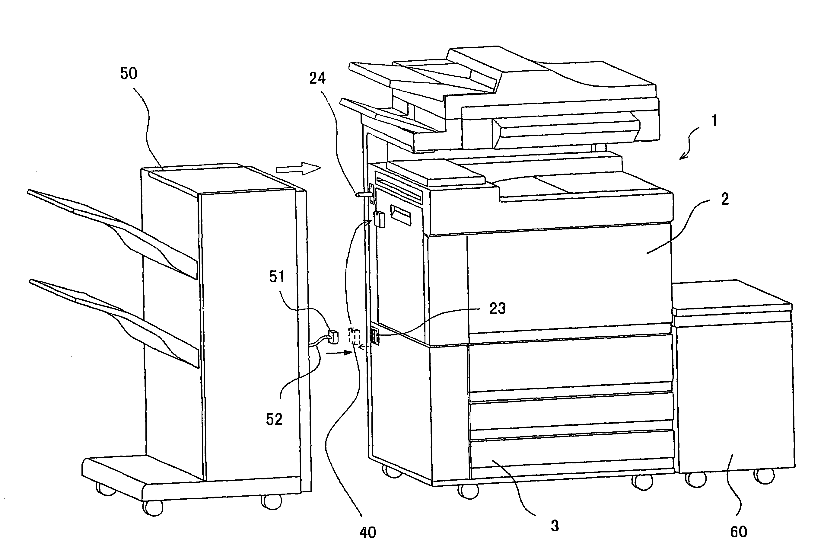
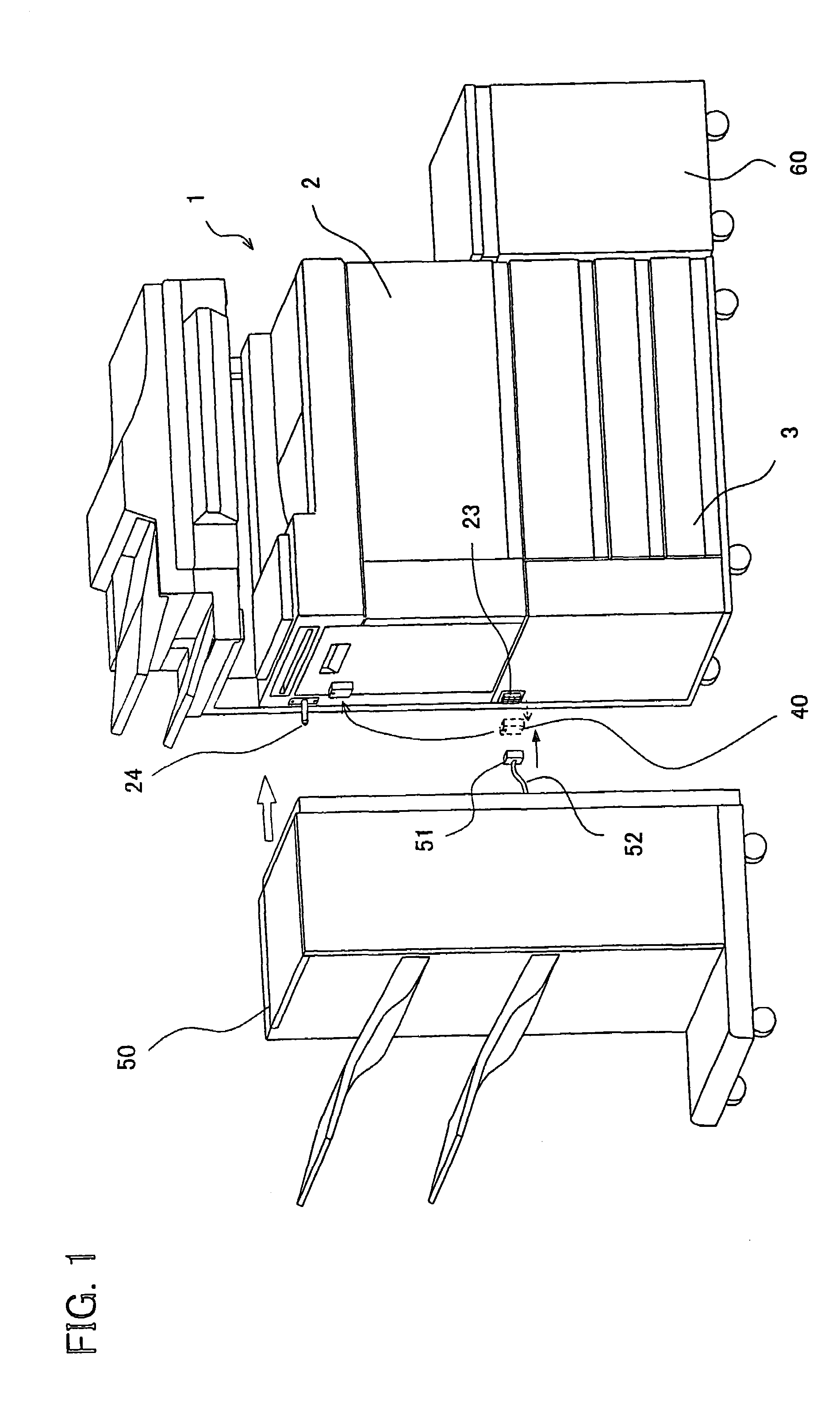
[0024]FIG. 1 is an outside and perspective view illustrating an image forming device, a postprocessing device as option device, and an external cover when the postprocessing device is fitted to the image forming device.

[0025]As illustrated in FIG. 1, a postprocessing device having stapling function, punching function, and other functions (second device) 50 is fitted to an image forming device (first device) 1 on the paper ejection side (the side shown in the left-hand part of FIG. 1). A postprocessing device (second device) 50 is a device for extending a system of the image forming device 1. Further, a large-capacity paper feeder 60 is fitted to the other side of the image forming device 1 (the side shown in the right-hand part of FIG. 1). The large-capacity paper feeder 60 will be described later in the Second Embodiment.

[0026]As illustrated in FIG. 1, the image formi...

second embodiment

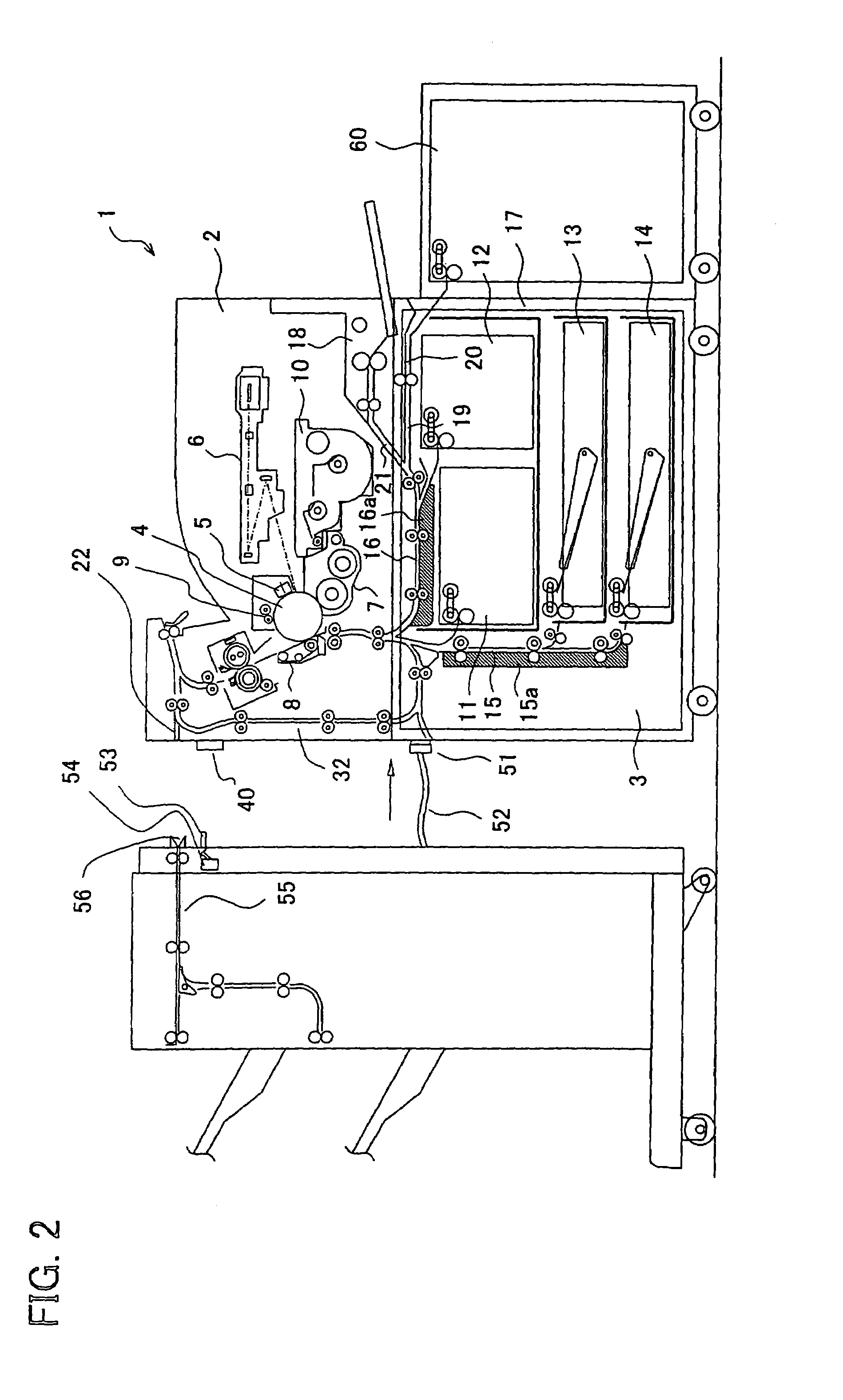
[0081]The following will describe another embodiment according to the present invention with reference to FIGS. 2 through 6. Note that, for the purpose of explanation, members having the same functions as those described in the First Embodiment are given the same reference numerals and explanations thereof are omitted here.

[0082]As illustrated in FIG. 2, the paper feed unit 3 of the image forming device (first device) 1 is fitted (connected) to the large-capacity paper feeder (second device) 60 as a fourth recording medium supplying section. The capacity of the large-capacity paper feeder 60 is set to be larger than those of other paper feed trays 11 through 14. A sheet of paper fed from the large-capacity paper feeder 60 passes through a transport path 20 and is guided to the printer section 2 through the transport path 19 and the transport 16. Note that, the transport path 20 is a transport path, provided to the paper feed unit 3, for first receiving a transporting target such as ...


PUM


Abstract

A connector cover of the present invention serves a function as a cover for a connector when a postprocessing device is not fitted to a main unit of an image forming device. Further, when the postprocessing device is fitted to the main unit of the image forming device, the connector cover is secured at the other position while maintaining the function as a cover for the connector, and serves a function as a shock-absorbing member with respect to the actuator which is provided in the postprocessing device. This makes it possible to secure a good appearance of the image forming device and make effective use of resources.

Description

[0001]This Nonprovisional application claims priority under 35 U.S.C. § 119(a) on Patent Application No. 2003 / 112698 filed in Japan on Apr. 17, 2003, the entire contents of which are hereby incorporated by reference.FIELD OF THE INVENTION[0002]The present invention relates to an external cover included in a main unit of an image forming device or the like including printer, facsimile, and copier, and when an option device or the like is not fitted to the main unit, covering a connecting part (attaching part) between the main unit and the option device, e.g. paper-receiving port, and relates to an image forming device including the external cover.BACKGROUND OF THE INVENTION[0003]Conventionally, a peripheral device such as postprocessing device and large-capacity paper feeder (hereinafter referred to as option device) would be fitted to a main unit of an image forming device in response to user's demand.[0004]Because of this, the main unit of the image forming device includes a commun...

Claims


Application Information

Patent Timeline
IPC IPC(8): G03G15/00G03G21/16
CPCG03G21/1652G03G2221/169G03G2221/1696
Inventor TOKISHIGE, KIYOSHIOKADA, NAOFUMINAGATA, JINICHIOHGITA, TOSHIKINANBA, TOYOAKI
Owner SHARP KK
Learn More