
Flat panel display wall mounting system

a technology for mounting systems and flat panels, which is applied in the direction of building scaffolds, machine supports, other domestic objects, etc., can solve the problems of difficulty in accessing the back side of the flat panel display in connection with servicing the flat panel display

Inactive Publication Date: 2007-11-27
BRETFORD MFG
View PDF11 Cites 104 Cited by
  • Summary
  • Abstract
  • Description
  • Claims
  • Application Information

AI Technical Summary

Benefits of technology

Facilitates easy access to the rear of the display for maintenance and adjustment of the display's pitch, ensuring the system remains secure and functional.

Problems solved by technology

However, once the flat panel display has been connected to the mounting system, it is difficult to access the back side of the flat panel display in connection with servicing the flat panel display.

Method used


Image

  • Flat panel display wall mounting system
  • Flat panel display wall mounting system
  • Flat panel display wall mounting system

Examples


Embodiment Construction

[0018]The following detailed description sets forth numerous specific details to provide a thorough understanding of the invention. However, those skilled in the art will appreciate that the invention may be practiced without these specific details. In other instances, well-known methods, procedures, components, and dimensions, have not been described in detail so as not to obscure the invention.

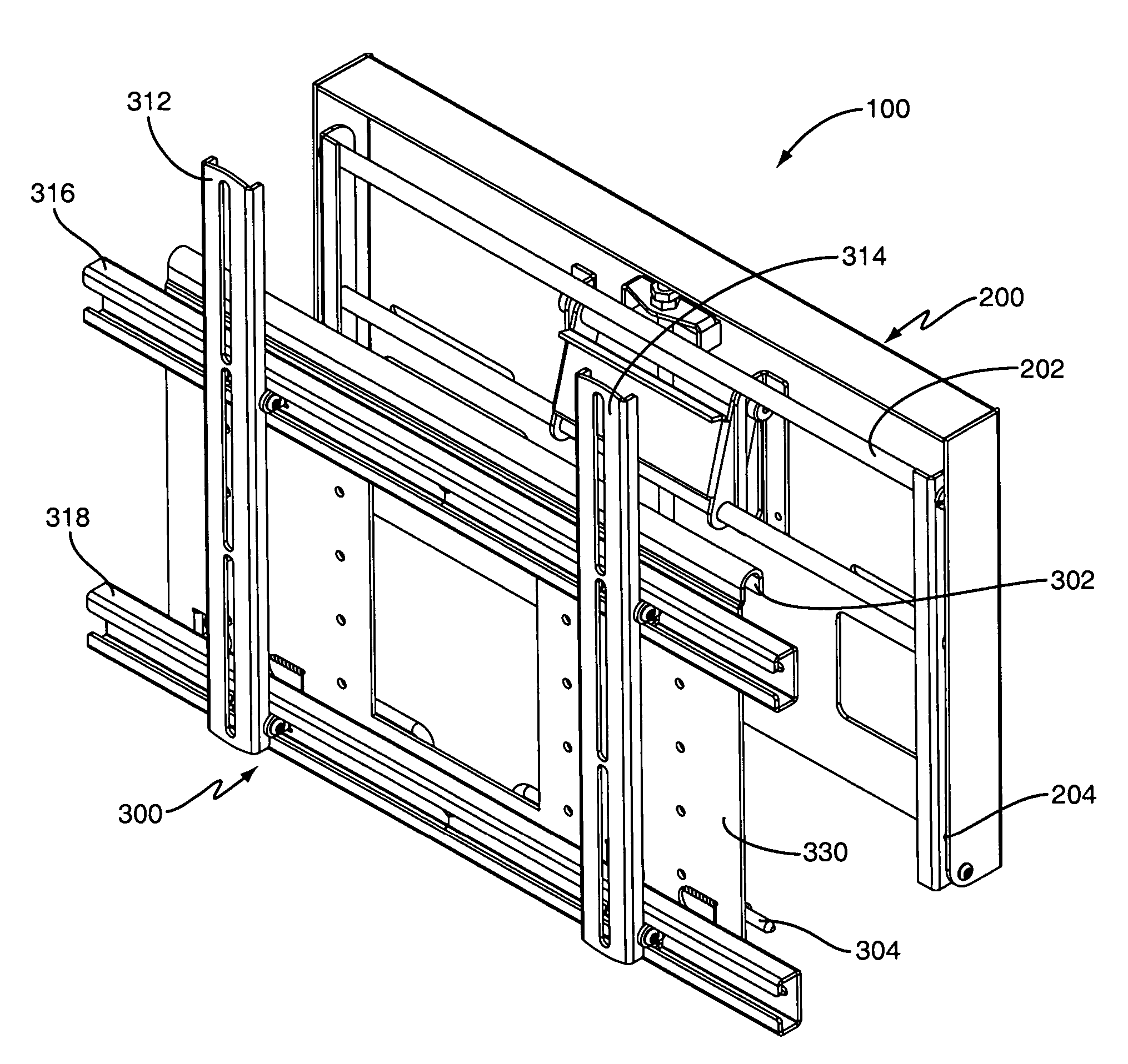
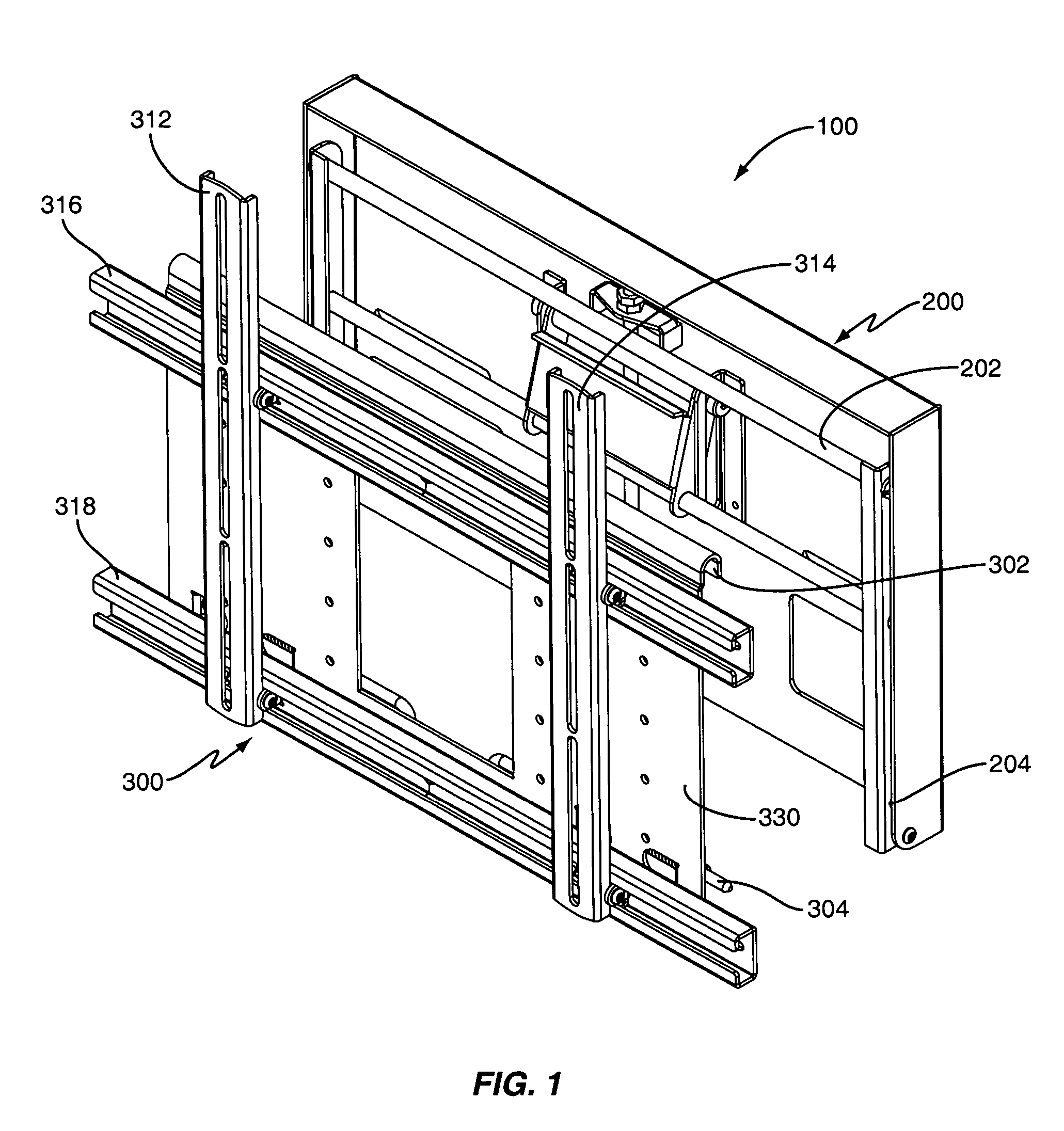
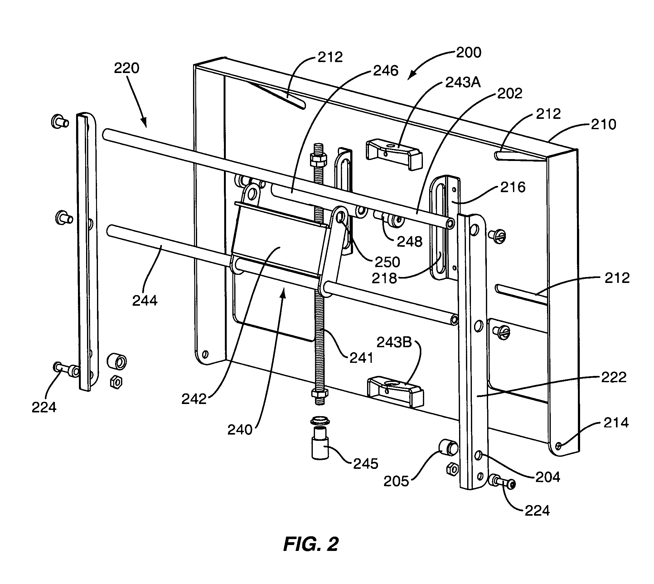
[0019]FIG. 1 illustrates an expanded perspective view of a flat panel display wall mounting system according to an embodiment of the invention. As shown in FIG. 1, the flat panel display WMS 100 includes a wall plate assembly 200 and a flat panel display mounting rack assembly 300. A U-shaped channel 302 is formed on the flat panel display mounting rack assembly 300 and configured to engage a bar 202 on the wall plate assembly so that the two structures (200, 300) may be joined during installation.

[0020]To install a flat panel display on a wall, the wall plate assembly 200 and the flat panel...


PUM


Abstract

A flat panel display wall mounting system includes a wall plate assembly connected to a flat panel display mounting rack assembly. The wall plate assembly and the mounting rack assembly are able to be separated to facilitate mounting on a wall. Specifically, the wall plate assembly may mounted on a wall and leveled, while the mounting rack assembly may be attached to a flat panel display while still on the ground. The flat panel display may then be hung on the wall plate assembly. A pitch assembly is provided to adjust the pitch of the flat panel display once hung on the wall plate assembly. A pin connection mechanism is provided to enable the mounting rack assembly to be pivoted out from the wall plate assembly so that the rear area of the flat panel display may be accessed for servicing while the flat panel display is mounted on the wall mounting system.

Description

CROSS-REFERENCE TO RELATED APPLICATIONS[0001]This application claims the benefit of prior provisional application No. 60 / 675,757, filed Apr. 28, 2005, the content of which is hereby incorporated herein by reference.BACKGROUND OF THE INVENTION[0002]1. Field of the Invention[0003]The present invention relates to display mounting systems and, more particularly, to a flat panel display wall mounting system.[0004]2. Description of the Related Art[0005]Flat panel displays, such as televisions and computer monitors, may be formed using many technologies. Currently, Liquid Crystal Displays (LCDs) and plasma displays are mass marketed as flat panel displays, although other flat panel display technologies also exist and may be developed over time.[0006]Flat panel displays may be supported on desk stands, wall mounts, pole mounts, or may be supported in numerous other ways. For example, the displays may be mounted individually or in groups on a horizontal surface such as a desk, table, floor o...

Claims


Application Information

Patent Timeline
Patent Type & Authority Patents(United States)
IPC IPC(8): E04G3/00
CPCF16M11/10F16M11/2092F16M13/02Y10S248/917Y10S248/921
Inventor PETRICK, CHRISTOPHERCOON, ROBERTDOAN, JIMMY-QUANG VIETKOURI, SCOTTGUNDERSON, BJORNDAVIRRO, NIC
Owner BRETFORD MFG
Learn More