
Knockdown attachment mechanism for a reclining chair

a technology for reclining chairs and attachment mechanisms, which is applied in the field of furniture industry, can solve the problems of difficult use of prior inspection assembly mechanisms, time-consuming, and requiring a long period of time for assembling and disassembling, and achieves the effect of quick and easy approach

Active Publication Date: 2007-12-11
L & P PROPERTY MANAGEMENT CO
View PDF8 Cites 12 Cited by
  • Summary
  • Abstract
  • Description
  • Claims
  • Application Information

AI Technical Summary

Benefits of technology

This solution streamlines the assembly and disassembly process, reducing labor time and minimizing the risk of lost components, while ensuring accurate fitting and quality control in chair manufacturing and shipping.

Problems solved by technology

Prior inspection assembly mechanisms were often difficult to use and time consuming, requiring bolting one part to another or snapping interlocking spring clip pieces together, then loosening the bolts or unsnapping the interlocked parts.
This assembly mechanism of the prior art is one of many that require a lengthy period of time assembling and disassembling.

Method used


Image

  • Knockdown attachment mechanism for a reclining chair
  • Knockdown attachment mechanism for a reclining chair
  • Knockdown attachment mechanism for a reclining chair

Examples


Embodiment Construction

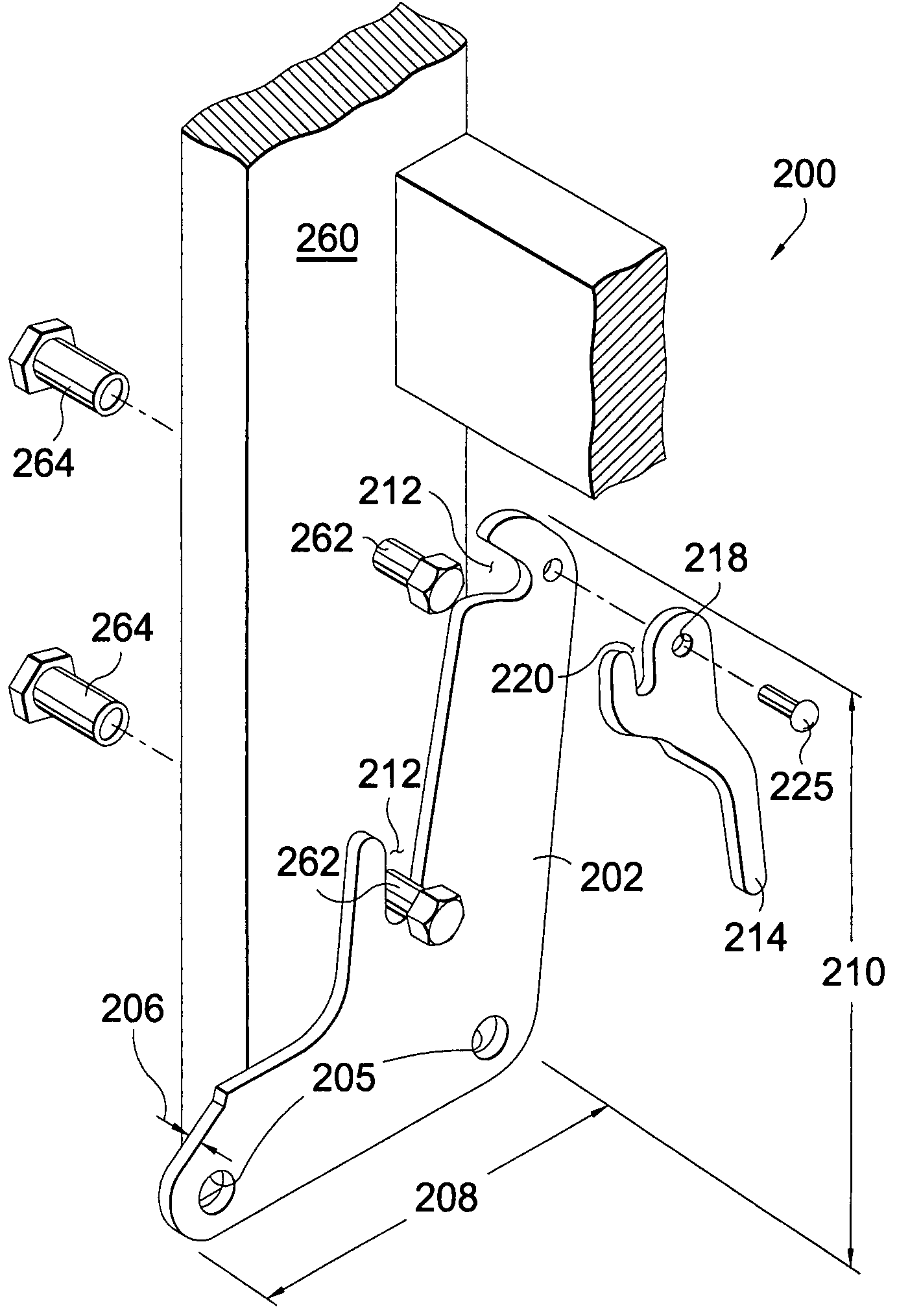
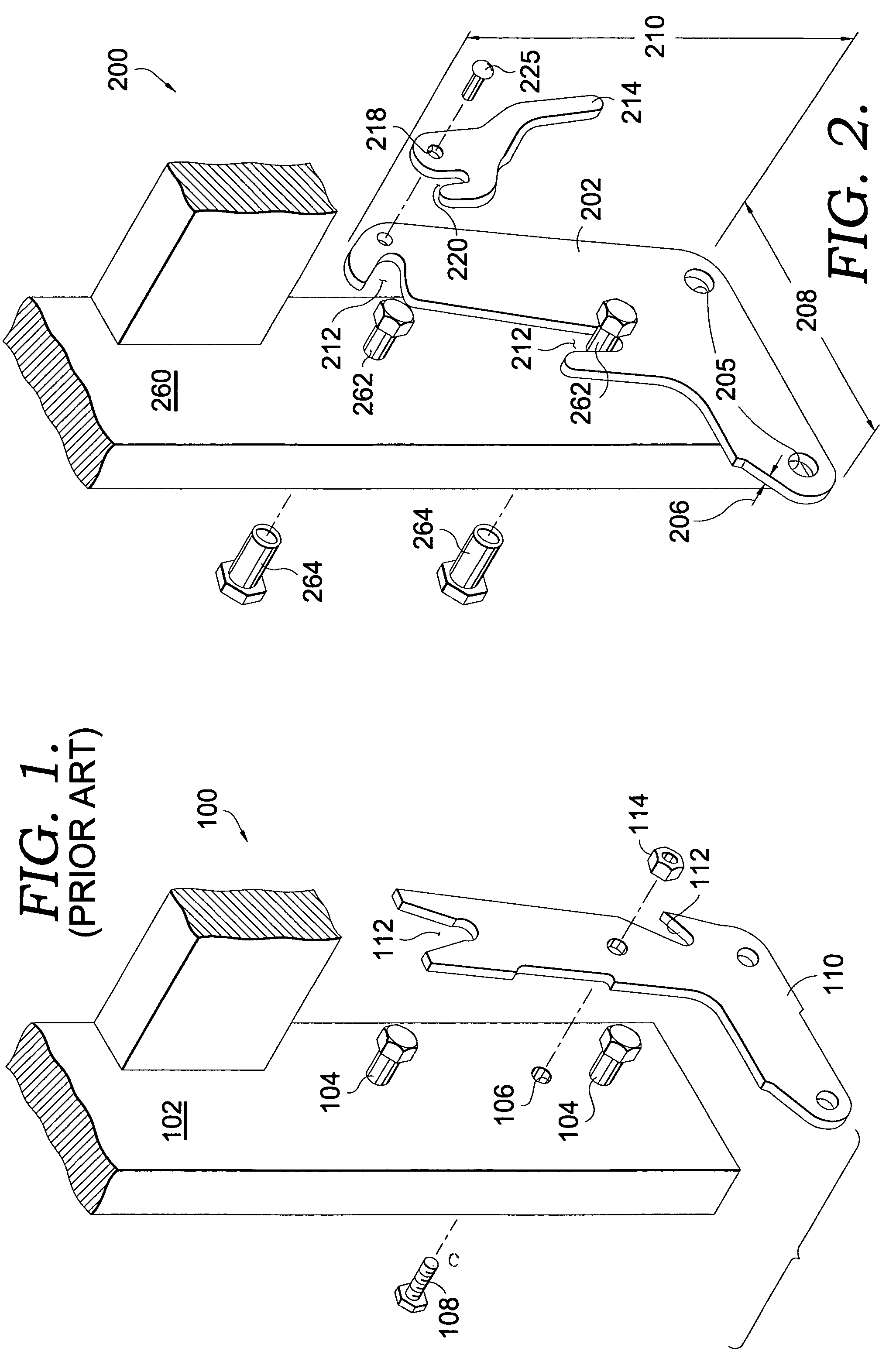
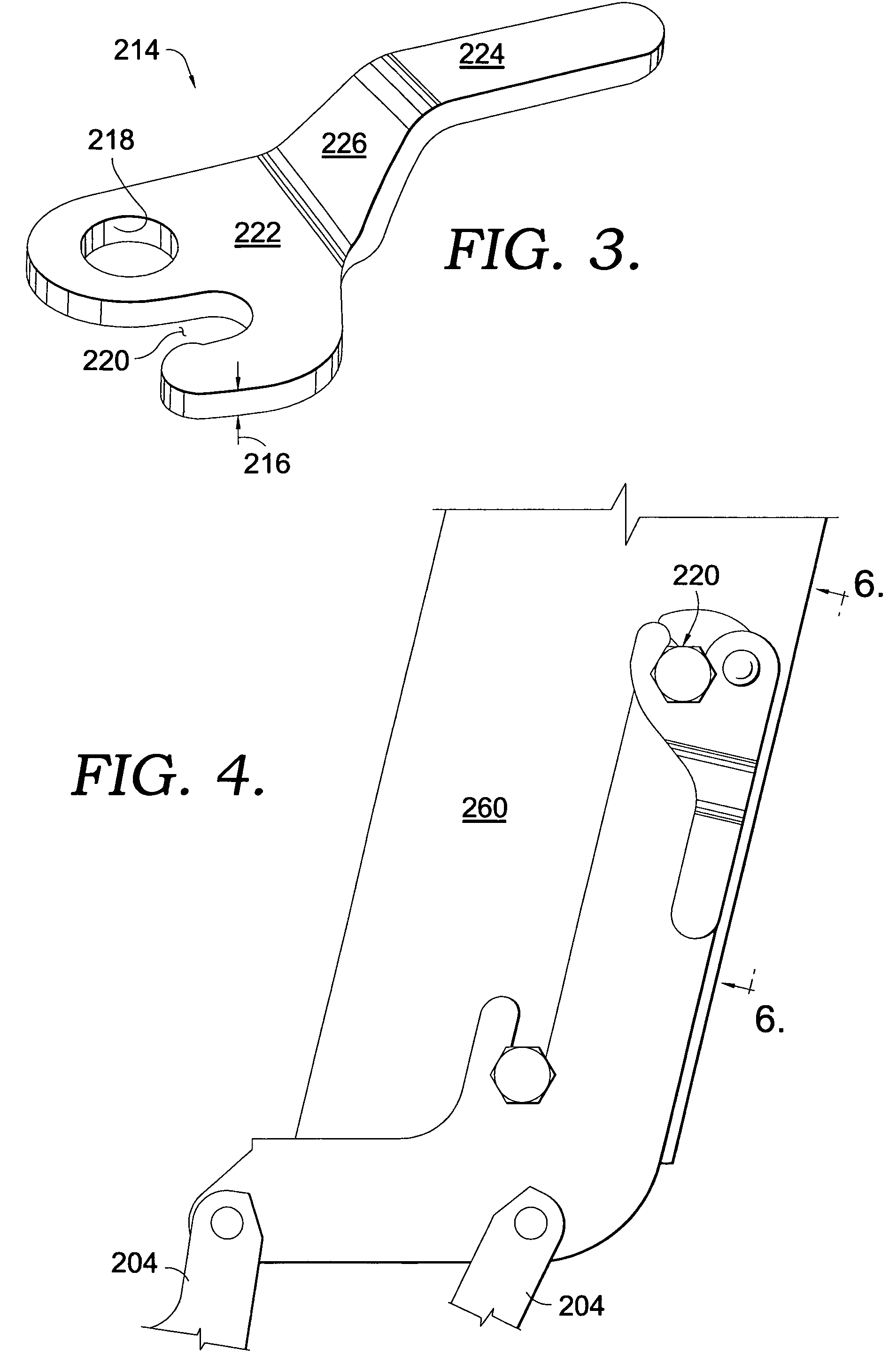
[0016]The present invention will now be described in greater detail with specific reference to FIGS. 2-6. Referring now to FIG. 2, a mechanism 200 for coupling a seat back to a base mechanism is shown. Mechanism 200 includes a coupling plate 202 connected to a base 204 (FIG. 5). The coupling plate 202 has a first thickness 206, a first length 208, a first height 210, and a plurality of first slots 212 formed in first thickness 206. In the embodiment shown, there are two slots 212. Coupling plate 202 is connected to base mechanism 204 at base holes 205, as best seen in FIGS. 4 and 5.

[0017]With reference now to FIGS. 2 and 3, mechanism 200 further comprises a locking plate 214 that has a second thickness 216, hole 218, and a second slot 220 formed therein. Locking plate 214 generally includes a first portion 222, a second portion 224 that is generally parallel to first portion 222, and a connecting section 226 that is oriented at an angle relative to first portion 222 to connect first...


PUM


Abstract

A chair is disclosed having a mechanism for assembling and disassembling a seatback thereto. The mechanism, which is fixed to the base of the chair, comprises a coupling plate having slots for receiving bolts from the seatback seat posts. Rotatably coupled to the coupling plate is a locking plate that when rotated about a fastener, secures a bolt from the seat post into slots in the locking plate and coupling plate, thereby securing the seatback to the base of the chair.

Description

CROSS-REFERENCE TO RELATED APPLICATIONS[0001]Not applicable.STATEMENT REGARDING FEDERALLY SPONSORED RESEARCH OR DEVELOPMENT[0002]Not applicable.TECHNICAL FIELD[0003]The present invention relates to the furniture industry. More particularly, the present invention discloses a mechanism and apparatus for securing a backrest onto a chair.BACKGROUND OF THE INVENTION[0004]In the furniture industry, designers and manufacturers must settle on a design that is appealing to the consumer in terms of visual appearance, comfort, and price, yet is manufacturer-friendly. As economic conditions change, more furniture manufacturers are sending their work to areas overseas that have lower labor costs in order to maximize profits, even though that requires shipping their products back to the United States. One aspect of the manufacturing process in which cost savings can be obtained is through more cost-effective packaging and shipping. For example, these costs can be controlled by shipping furniture ...

Claims


Application Information

Patent Timeline
Patent Type & Authority Patents(United States)
IPC IPC(8): A47C7/42
CPCA47C7/42
Inventor WIECEK, GLENN N.
Owner L & P PROPERTY MANAGEMENT CO
Learn More