Forming tool apparatus with pivoting wall segment

Active Publication Date: 2007-12-11
GM GLOBAL TECH OPERATIONS LLC
View PDF7 Cites 17 Cited by
  • Summary
  • Abstract
  • Description
  • Claims
  • Application Information

AI Technical Summary

Problems solved by technology

However, in many instances this would compromise the desired shape of the finished formed article and it is therefore necessary to design the formed article with more complex shapes that require that the forming tool have a negative draft angle by undercutting a wall of the forming tool cavity.
In this case the finished article is locked within the forming tool and cannot be removed.

Method used


Image

  • Forming tool apparatus with pivoting wall segment
  • Forming tool apparatus with pivoting wall segment
  • Forming tool apparatus with pivoting wall segment

Examples


Embodiment Construction

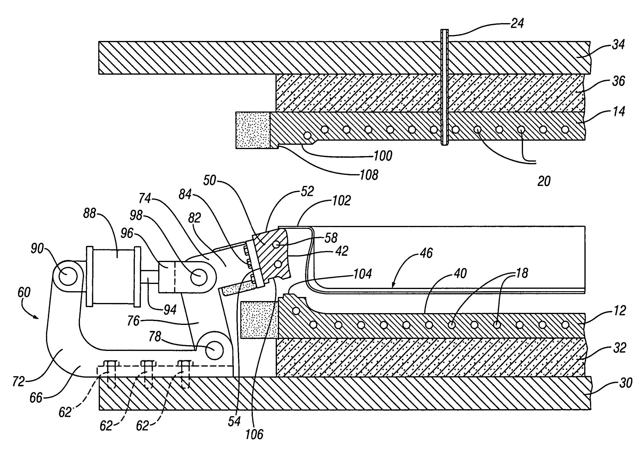
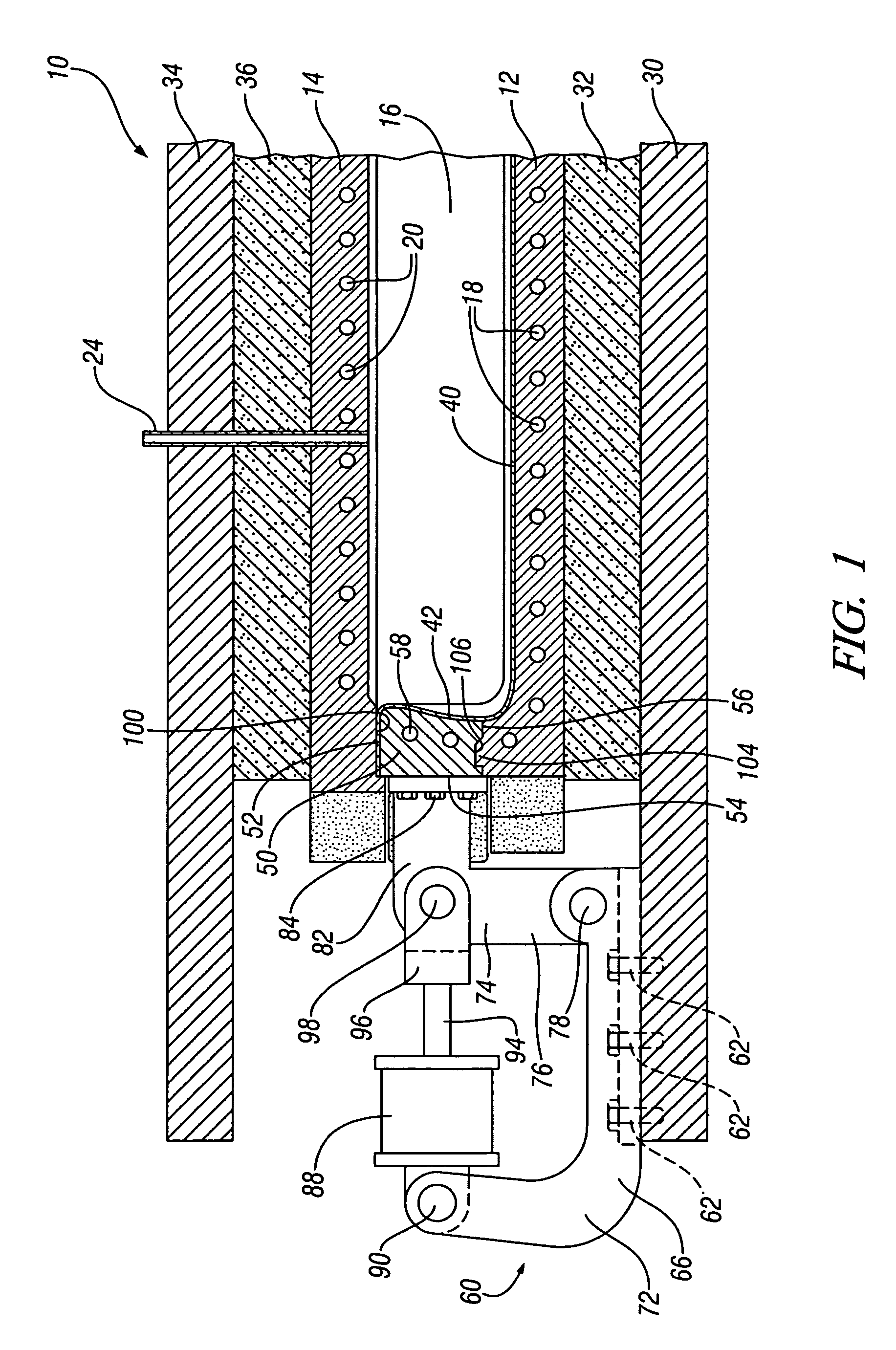
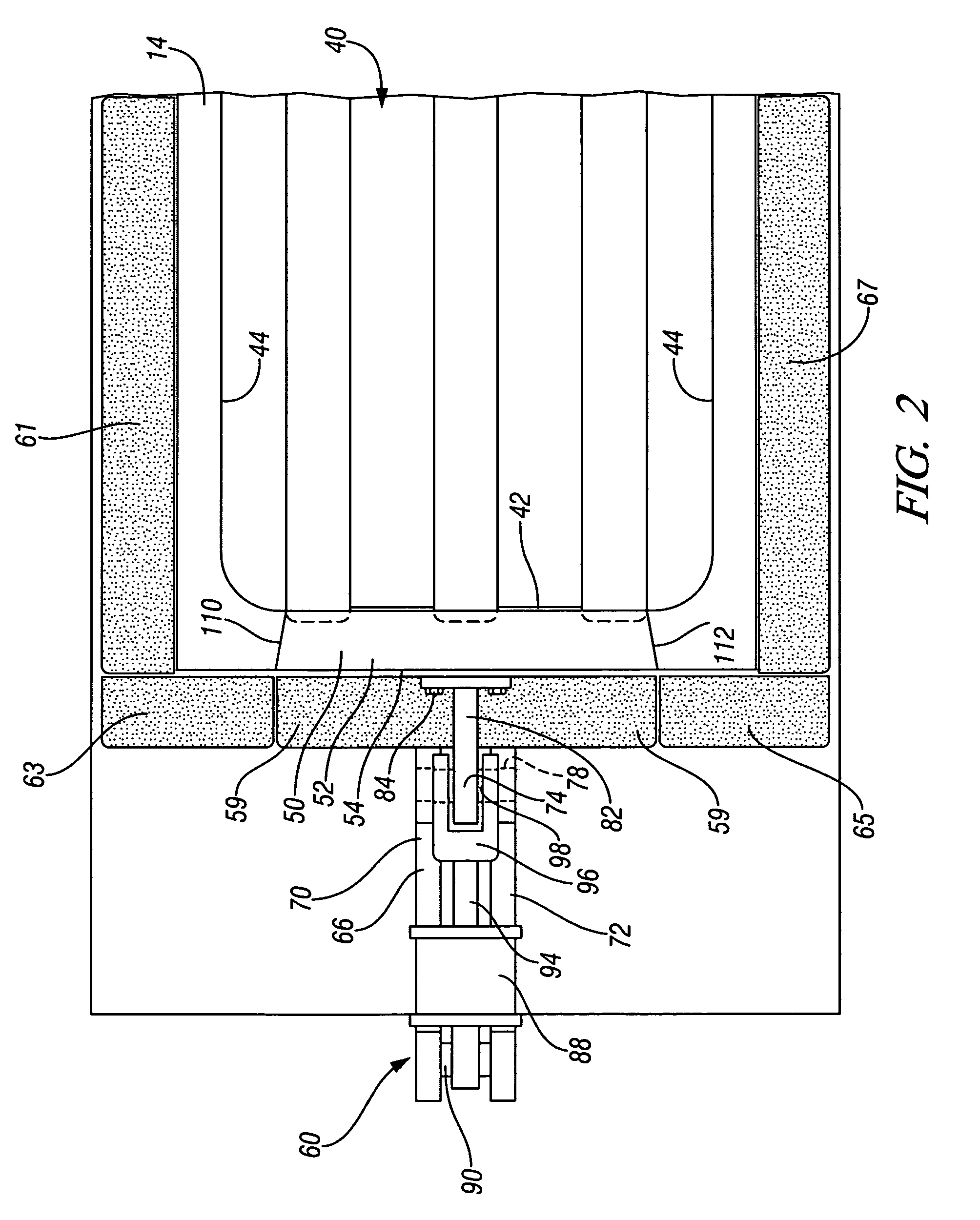
[0012]The following description of a particular embodiment is exemplary in nature and is in no way intended to limit the invention, its application, or uses.

[0013]Referring to FIG. 1, there is shown a forming apparatus 10 including a lower forming tool 12 and an upper forming tool 14 that are closed relative one another to define a forming tool cavity 16. The particular forming tool shown in FIG. 1 is for the forming of a sheet of heated metal in a process commonly known as superplastic forming or quick plastic forming. Accordingly the forming tools 12 and 14 have heating elements 18 and 20 embedded therein to maintain the temperature of a preheated sheet metal blank that will be draped across the lower forming tool when the forming tools 12 and 14 are in open positions relative one another. The upper forming tool 14 has a gas inlet 24 through which high pressure gas will be introduced after the upper forming tool 14 is lowered onto the lower forming tool 12 to force the preheated s...


PUM

PropertyMeasurementUnit
negative draft angleaaaaaaaaaa
shapeaaaaaaaaaa
interlocking structuresaaaaaaaaaa

Abstract

An improved forming tool apparatus for forming an article having a negative draft angle that locks the formed article within the forming tool. First and second forming tools are closed relative one another to define a forming tool cavity in which the article is formed and opened for removal of the formed article from the forming tool cavity. The first forming tool has a removable cavity wall segment having an undercut cavity wall that provides a desired shape to the formed article but locks the formed article against removal from the forming tool cavity. A pivot linkage normally establishes the removable wall segment in a forming position in which the undercut wall is poised for forming of the article and selectively pivots the removable wall segment out of the forming position when the forming tools are opened so that the undercut wall is pivotally lifted and releases the formed article for removal from the cavity.

Description

FIELD OF THE INVENTION[0001]The present invention relates to a forming tool for making a formed article and more particularly to a forming tool apparatus for the forming of a sheet article having a negative draft angle that locks the formed article within the forming tool.BACKGROUND OF THE INVENTION[0002]It is well known to form manufactured articles within a forming tool or that includes a first forming tool and a second forming tool that define a cavity there between in the shape of the finished article. The forming tools are typically mounted in a press with one forming tool being stationary and the other forming tool being movable between a closed position in which the forming tool cavity is defined and an open position so that the finished article can be removed from the forming tool. Many types of forming processes are known. For example the finished article may be molded of a fluid plastic material that is injected or blown or vacuumed into the forming tool, or molded of a sh...

Claims


Application Information

Patent Timeline
Patent Type & Authority Patents(United States)
IPC IPC(8): B29C45/44
CPCB21D26/055Y10S425/058
Inventor KRUGER, GARY A.KONOPNICKI, MARK G.CARSLEY, JOHN E.
Owner GM GLOBAL TECH OPERATIONS LLC
Why Eureka
Try Eureka