Roof Structure of a Vehicular Body

a technology of roof structure and vehicular body, which is applied in the direction of roof, vehicle sub-unit features, transportation and packaging, etc., can solve the problems of not being able louder noise generated by the roof panel, and inability to effectively restrain the vibration of the roof panel. , to achieve the effect of reducing the vibration of the roof panel, and reducing the noise of the roof panel

Active Publication Date: 2007-08-02
NISSAN MOTOR CO LTD
View PDF3 Cites 18 Cited by
  • Summary
  • Abstract
  • Description
  • Claims
  • Application Information

AI Technical Summary

Benefits of technology

[0009]According to the roof structure of the vehicular body constructed in accordance with the present invention, it is possible to broaden a range in which the roof reinforcement supports the roof panel. It is also possible to effectively restrain the vibration of the roof panel when the resonance occurs in a frame of a vehicle due to the vibration of the engine, etc. In this regard, the plurality of roof reinforcements have a greater relative width adjacent a front of the vehicular body than adjacent a rear of the vehicular body and a smaller relative spacing between the plurality of roof reinforcements adjacent the front of the vehicular body than the rear of the vehicular body

Problems solved by technology

When the amplitude of the roof panel vibration increases due to resonance, the noise generated from the roof panel becomes louder and a muffled sound may generate.
Accordingly, when a range in which the roof reinforcement supports the roof panel is small and the resonance occurs at the vehicular frame (i.e., a body structure) due to the vibration of an engine, etc., it is not possible to effectively restrain the vibration of the roof panel.

Method used


Image

  • Roof Structure of a Vehicular Body
  • Roof Structure of a Vehicular Body
  • Roof Structure of a Vehicular Body

Examples


first preferred embodiment

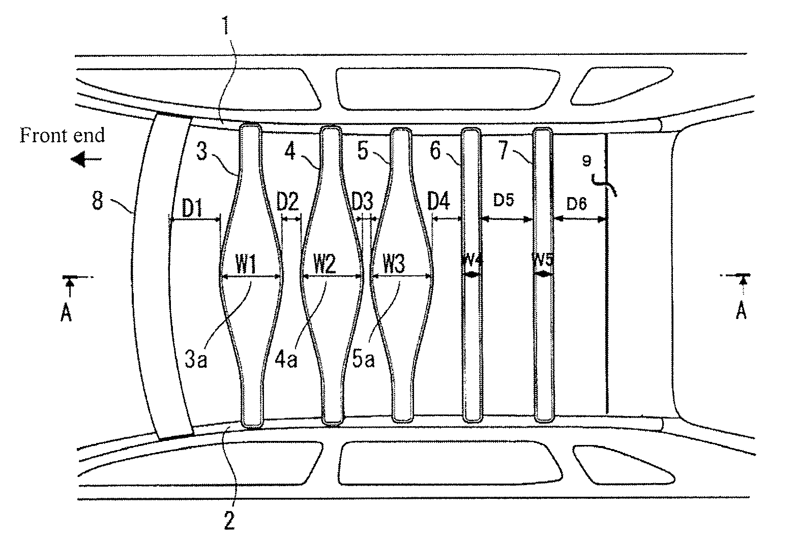
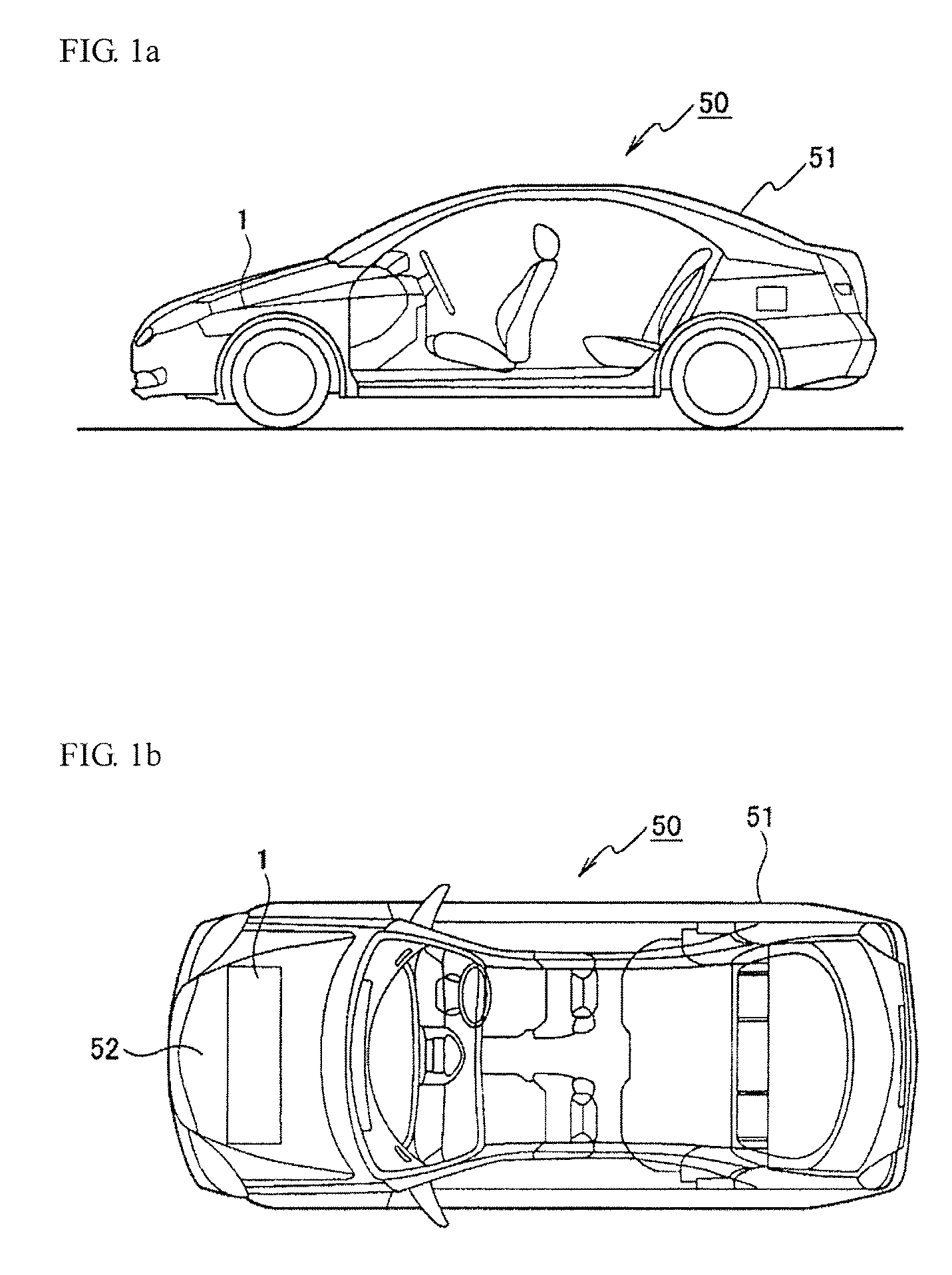
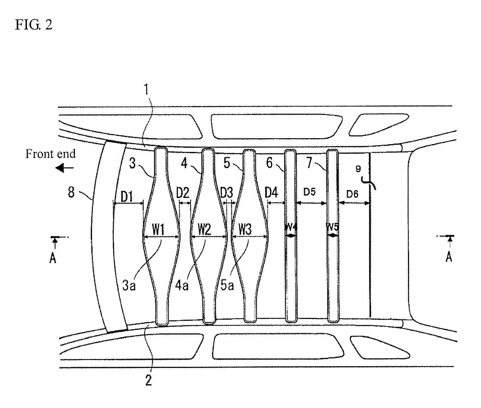
[0020]FIGS. 1a and 1b illustrate an external appearance of a vehicular body having an engine as a power source, and show an example of the vehicular body (an automotive vehicle) having a roof structure constructed in accordance with a first preferred embodiment of the present invention. FIG. 2 is a schematic top view showing a roof structure of the vehicular body (automotive vehicle) constructed in accordance with the first preferred embodiment of the present invention. FIG. 3 is a cross-sectional view of FIG. 2 taken along the length of the vehicular body (i.e. along line A-A). Further, the left portion of FIG. 2 shows a front side (end) of the vehicular body, whereas the right portion thereof shows a rear side (end) of the vehicular body.

[0021]FIG. 1a is a side view of a vehicular body 50, whereas FIG. 1b is a top view of the vehicular body 50. As shown in FIG. 1b, an engine compartment portion 52 is located in front of the vehicular body 50. The engine compartment portion 52 is f...

second preferred embodiment

[0036]FIG. 5 is a schematic top view showing a roof structure of a vehicular body (an automotive vehicle) constructed in accordance with a second preferred embodiment of the present invention. FIG. 6 is a cross-sectional view of FIG. 5 taken along the line B-B. Further, the left portion of FIG. 5 shows a front end of the vehicular body (an automotive vehicle), whereas the right portion thereof shows a rear end of the vehicular body (an automotive vehicle). Like reference numerals designate like features in the first preferred embodiment of the present invention, and the repetitive explanations thereof will be omitted herein.

[0037]In the first preferred embodiment of the present invention, the wide portions are formed at each center of the three roof reinforcements positioned at the front end. In contrast, in the second preferred embodiment of the present invention (as shown in FIGS. 5 and 6), among a plurality of roof reinforcements 3, 4, 5, 6 and 7 (five roof reinforcements in FIG....

third preferred embodiment

[0045]FIG. 7 is a schematic top view showing a roof structure of a vehicular body (an automotive vehicle) constructed in accordance with a third preferred embodiment of the present invention. FIG. 8 is a cross-sectional view of FIG. 7 taken along the line C-C. Further, the left portion of FIG. 7 shows a front end of the vehicular body (an automotive vehicle), while the right portion thereof shows a rear end of the vehicular body (an automotive vehicle). Like reference numerals designate like features in the first and second preferred embodiments of the present invention, and the repetitive explanations thereof will be omitted herein.

[0046]In the third preferred embodiment of the present invention (as shown in FIGS. 7 and 8), among a plurality of roof reinforcements 3, 4, 5, 6 and 7 (five reinforcements in FIG. 5) installed between the side roof rails 1, 2 at the right and left sides of a vehicular body, the widths of three roof reinforcements 3, 4 and 5 (which are positioned at the ...


PUM


Abstract

There is provided a roof structure of a vehicular body. The roof structure includes right and left side roof rails disposed on opposing sides of the vehicular body. The roof structure further includes a plurality of roof reinforcements installed in a spaced-apart relationship between the side roof rails and extending along a lateral direction across the vehicular body and a roof panel attached to the roof reinforcements, wherein at least one roof reinforcement of the plurality of roof reinforcements is a first roof reinforcement having a maximum width portion wider than a closest relative spacing between the first roof reinforcement and an adjacent roof reinforcement of the plurality of roof reinforcements on a first side of the first roof reinforcement.

Description

TECHNICAL FIELD[0001]The present invention relates to a roof structure of a vehicular body.BACKGROUND OF THE INVENTION[0002]A roof reinforcement serves as a roof framework and is mounted on right and left side roof rails along the lateral direction of an automotive vehicle. The roof reinforcement, which has a wide portion at its center, is located between front and rear roof rails (see Japanese Laid-Open Patent Publication No. 2001-301653; hereinafter, “Reference 1”).[0003]The roof reinforcement has a reversed hat-shaped cross-section for ensuring the strength and rigidity of a roof panel. A bottom surface of the roof panel is bonded to a flange portion of the roof reinforcement through the use of an adhesive.[0004]In a conventional roof structure in which the roof panel is bonded on the roof reinforcement by an adhesive, a resonance frequency that can significantly deform the framework of the vehicular body is close to a resonance frequency of the roof panel. Further, an amplitude ...

Claims


Application Information

Patent Timeline
Patent Type & Authority Applications(United States)
IPC IPC(8): B62D25/06
CPCB62D25/06B60Y2410/124B60Y2306/09
Inventor WATANABE, JUNTSUBOTA, YORIMASA
Owner NISSAN MOTOR CO LTD
Why Eureka
Try Eureka