Methods and apparatus for magnetic resonance imaging in inhomogeneous fields

a magnetic resonance imaging and inhomogeneous field technology, applied in the direction of reradiation, measurement using nmr, instruments, etc., can solve the problems of large power expenditure, inability to design the arrangement of coils, time-consuming and sar-intensive in vivo applications, etc., and achieve the effect of convenient measuremen

Active Publication Date: 2007-12-18
THE TRUSTEES OF THE UNIV OF PENNSYLVANIA
View PDF17 Cites 11 Cited by
  • Summary
  • Abstract
  • Description
  • Claims
  • Application Information

AI Technical Summary

Problems solved by technology

However, this requires a large expenditure of power and complicated, difficult to design arrangements of coils.
Though it is very good for spectroscopy of materials, it is too time consuming and SAR intensive for in vivo applications.
Further refinements of this method are presented herein for acquiring data that lead to a fairly standard 2d-reconstruction problem.

Method used


Image

  • Methods and apparatus for magnetic resonance imaging in inhomogeneous fields
  • Methods and apparatus for magnetic resonance imaging in inhomogeneous fields
  • Methods and apparatus for magnetic resonance imaging in inhomogeneous fields

Examples


first embodiment

[0067]In this first embodiment, the problem of imaging with an inhomogeneous background field without critical points is considered. A simplified model, with a background field, B0(x,y,z), of the form:

B0(x,y,z)=(b0−Gz){circumflex over (z)}  (7)

is considered for z∈[−zmax,zmax]. While G / b0 may be large, per unit distance, the field of view is constrained so that b0±Gzmax is also assumed to be large. This means that B0 is large within the field of view, and therefore, slowly varying perturbing fields, orthogonal to B0, can safely be ignored. There are many possibilities for the placement of coils to generate the gradients and RF-pulses needed to do imaging. In some circumstances, these coils could be placed around the sample, in other cases they could be placed on one side of the sample. For a preliminary analysis, it is assumed that the gradient in |B0| is parallel to the direction of B0. This simplifies the discussion, a little, but is not necessary to do the analysis. A similar anal...

second embodiment

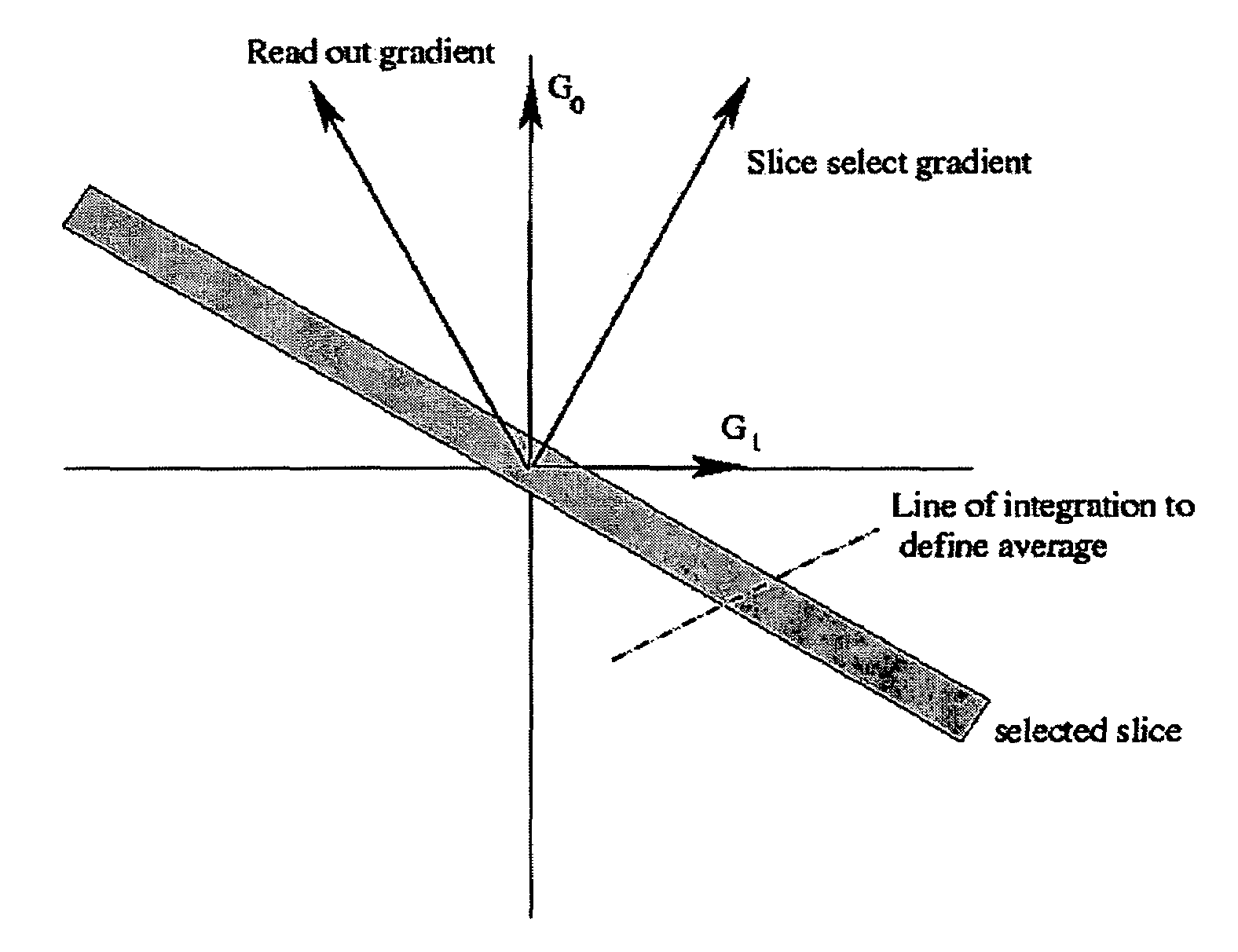
[0088]A second embodiment using a 2-dimensional imaging protocol will now be described. In this case, the permanent gradient is employed, along with a field of the form Gss=η1sG1+η2sG2, to define the slice selection direction, and a field transverse to this direction, Gre as the read out gradient. A third field of the form Gph=λ(η1pG1+η2pG2) is used as a phase encoding gradient. To describe the invention, a simple case is first considered wherein all of the gradients are linearly varying magnetic fields. As usual, it is assumed that the background field B0 is sufficiently strong throughout D that components of fields orthogonal to B0 have a very small effect on the measurements and can safely be ignored.

Analysis in the Linear Case

[0089]Let us suppose that B00=(0,0,b0) and let:

B0=(0,0,b0)+(*,*,gzz)=B00+G0

G1=(*,*,x) and G2=(*,*,y)  (22)

Here * is used to denote negligibly small field components orthogonal to (0,0,b0). The permanent field gradient is of the form:

Gz=(0,0,gz),  (23)

and we...


PUM


Abstract

Methods for providing practical magnetic resonance imaging systems that utilize non-homogeneous background fields, B0, as well as, possibly non-linear, gradient fields G1, G2 to make non-invasive measurements to determine, among other things, a spin density function. Two types of non-homogeneous background fields are considered: background fields B0 in which the function |B0| does not have a critical point within the field of view, and background fields B0 such that the function |B0| has a single critical point within the field of view. In the first case, an MR-imaging device may be constructed by using the permanent gradient in the background field, B0, as a slice select gradient, so long as particular criteria are met. In the second case, magnets may be constructed so that |B0| has an isolated non-zero local minimum. Using selective excitation, one can excite only the spins lying in a small neighborhood of this local minimum.

Description

CROSS-REFERENCE TO RELATED APPLICATIONS[0001]This application claims benefit to U.S. Provisional Application Nos. 60 / 663,937 filed Mar. 21, 2005 and 60 / 737,283 filed Nov. 16, 2005.GOVERNMENT SUPPORT[0002]The present invention was supported by the National Science Foundation under Grant Nos. NSF DMS99-70487, DMS02-07123, and DMS02-3705. The government may have certain rights in the invention.FIELD OF THE INVENTION[0003]The present invention relates to methods and apparatus for obtaining magnetic resonance images in inhomogeneous magnetic fields and, more particularly, to imaging with a background field B0 that varies both in magnitude and direction, both with and without critical points.BACKGROUND OF THE INVENTION[0004]In the standard approach to magnetic resonance imaging one uses a strong background field that is as homogeneous as possible. Commercial MR imaging magnets are homogeneous, within the field of view, to about 1 ppm. In “open” MRI systems, the field homogeneity is somewh...

Claims


Application Information

Patent Timeline
Patent Type & Authority Patents(United States)
IPC IPC(8): G01V3/00
CPCG01R33/48G01R33/445G01R33/3808
Inventor EPSTEIN, CHARLES L.MAGLAND, JEREMY
Owner THE TRUSTEES OF THE UNIV OF PENNSYLVANIA
Why Eureka
Try Eureka