Slab-selective RF coil for MR system

a mr system and rf coil technology, applied in the field of rf coils, can solve the problems of exposing the subject to excessive rf radiation, affecting the degree of electromagnetic energy, and the shape and homogeneity of their fields are often not suitable for a particular application

Active Publication Date: 2008-09-02
NORTHSHORE UNIV HEALTHSYST RES INST
View PDF8 Cites 13 Cited by
  • Summary
  • Abstract
  • Description
  • Claims
  • Application Information

AI Technical Summary

Benefits of technology

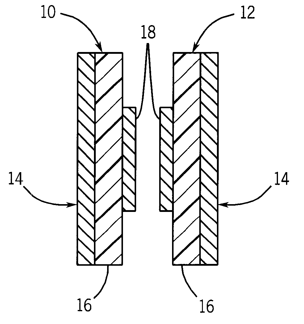
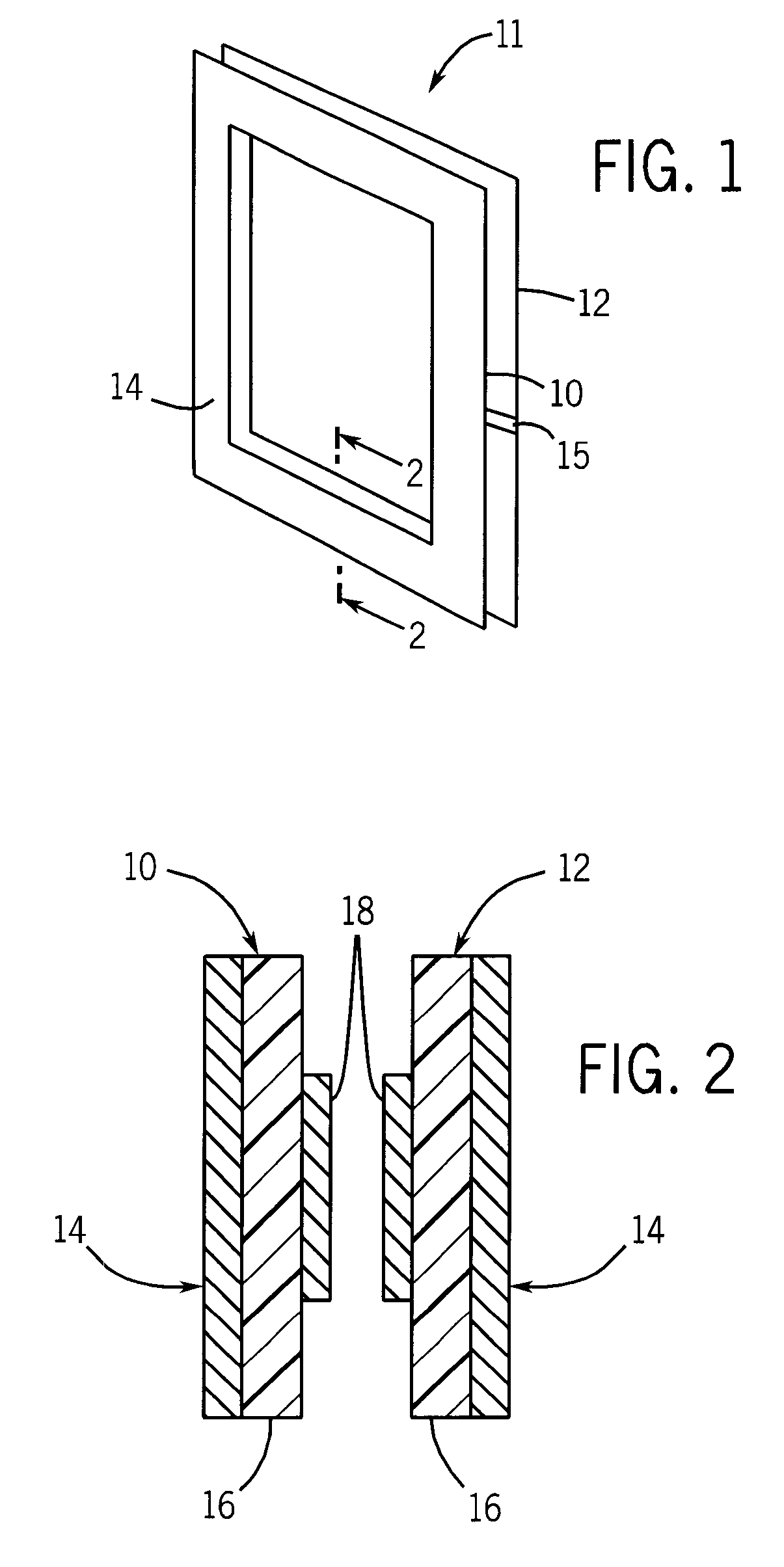
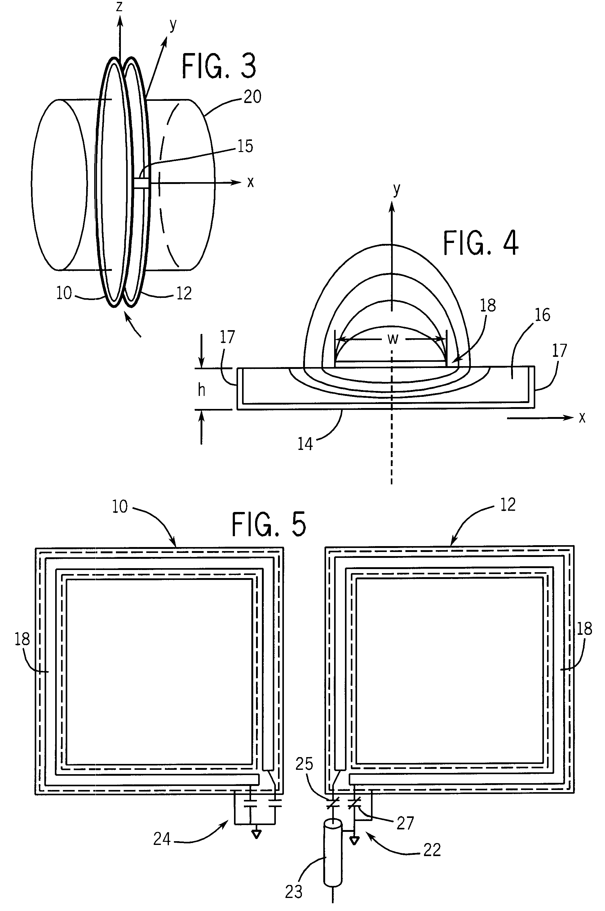
[0009]The present invention is an RF coil for a magnetic resonance system which produces a uniform RF magnetic field in a well defined slab through the subject. Such a slab can be made fairly thin, on the order of a few centimeters for example. MR data may be acquired from such a slab using higher amplitude and duration RF excitation pulses without exposing the subject to significant RF radiation outside the slab.
[0011]A general object of the invention is to provide an RF coil that has high sensitivity, high field homogeneity, and high power efficiency free from the effect of dielectric resonance at high magnetic fields (B0>3T), for delivering RF power and for detecting NMR RF signals. The RF coil of the present invention has the shape and size of a volume coil, but the volume is very thin such that a slab through the subject may be examined without exceeding SAR.

Problems solved by technology

While local coils do limit the region that is subject to RF excitation fields during a scan, the shape and homogeneity of their fields is often not appropriate for a particular application.
An issue with all RF coils used to generate the B1 field is the level of electromagnetic energy which can be absorbed by a human subject during a scan.
Some pulse sequences employ RF excitation pulses of long duration which may expose the subject to excessive RF radiation.
This is particularly problematic at high polarizing magnetic field strengths where SAR limits are easily exceeded.

Method used


Image

  • Slab-selective RF coil for MR system
  • Slab-selective RF coil for MR system
  • Slab-selective RF coil for MR system

Examples


Embodiment Construction

[0023]Referring particularly to FIG. 11, an RF coil 11 according to the invention is employed in an MRI system such as MRI system 100, which includes a workstation 110 having a display 112 and a keyboard 114. The workstation 110 includes a processor 116 and provides the operator interface which enables scan prescriptions to be entered into the MRI system.

[0024]The workstation 110 is coupled to four servers: a pulse sequence server 118, a data acquisition server 120, a data processing server 122, and a data store server 123. The data store server 123 is for example performed by the workstation processor 116 and associated disc drive interface circuitry. The remaining three servers 118, 120 and 122 can be performed by separate processors mounted in a single enclosure and interconnected using a 64-bit backplane bus. The pulse sequence server 118 can employ a commercially available microprocessor and a commercially available quad communication controller. The data acquisition server 120...


PUM


Abstract

An RF coil includes two coil portions that are spaced apart to define a slab therebetween. Each coil portion is a microstrip transmission line formed as a loop wherein the microstrip includes a conductive strip disposed on one side of a dielectric material and a ground plane disposed on the other side of the dielectric material. When energized, a uniform RF field is produced in the slab. An array of such RF coils arranged back to back can be formed to allow for the selective excitation of a desired slab.

Description

CROSS REFERENCES TO RELATED APPLICATIONS[0001]This application claims priority to U.S. provisional patent application Ser. No. 60 / 756,271, filed on Jan. 4, 2006, and titled “SLAB-SELECTIVE RF COIL FOR MR SYSTEM”.STATEMENT REGARDING FEDERALLY SPONSORED RESEARCH[0002]This invention was made with government support under Grant No. EB002912 awarded by the National Institutes of Health. The United States Government has certain rights in this invention.FIELD OF THE INVENTION[0003]The field of the invention is Magnetic Resonance Imaging (MRI) and Magnetic Resonance Spectroscopy (MRS), and particularly RF coils for use in such systems.BACKGROUND OF THE INVENTION[0004]When a substance such as human tissue is subjected to a uniform magnetic field (polarizing field B0), the individual magnetic moments of the spins in the tissue attempt to align with this polarizing field, but precess about it in random order at their characteristic Larmor frequency. If the substance, or tissue, is subjected to...

Claims


Application Information

Patent Timeline
Patent Type & Authority Patents(United States)
IPC IPC(8): G01V3/00
CPCG01R33/34007G01R33/34046G01R33/422G01R33/3415G01R33/3456G01R33/3635G01R33/34061G01R33/288
Inventor ZHANG, HUIMING
Owner NORTHSHORE UNIV HEALTHSYST RES INST
Why Eureka
Try Eureka