Optical methods for remotely measuring objects

a technology for remote measurement and objects, applied in the field of optical methods for remotely measuring objects, can solve the problem of not having a cost-effective solution for remotely measuring the length of an edg

Active Publication Date: 2007-12-18
MICROSOFT TECH LICENSING LLC
View PDF14 Cites 369 Cited by
  • Summary
  • Abstract
  • Description
  • Claims
  • Application Information

AI Technical Summary

Benefits of technology

[0014]Embodiments of the invention include a camera system, one or more structured light source, or a special pattern that is already drawn on the object under measurement. In one embodiment, the system projects the light source(s) on the surface that the user wants to measure the length of. The camera system uses image-processing techniques to measure the real length of the projected pattern. The method can be extended to measure the volumes of boxes by projecting multiple light sources. Similarly; the method can be generalized by allowing a moving light generator to measure the angles on planar surfaces, or to measure various geometric attributes (such as area, perimeter,...

Problems solved by technology

Although methods exist for measurement of objects, there does not exist a cost-effective so...

Method used


Image

  • Optical methods for remotely measuring objects
  • Optical methods for remotely measuring objects
  • Optical methods for remotely measuring objects

Examples


Embodiment Construction

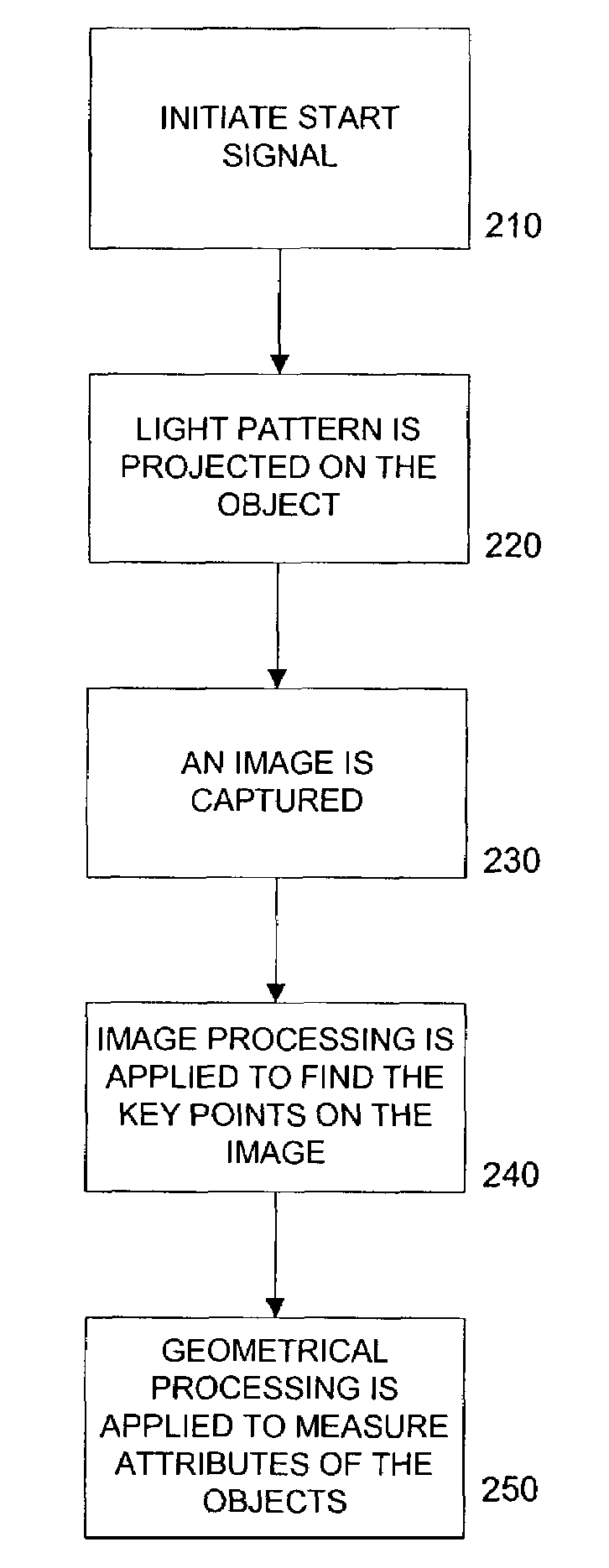
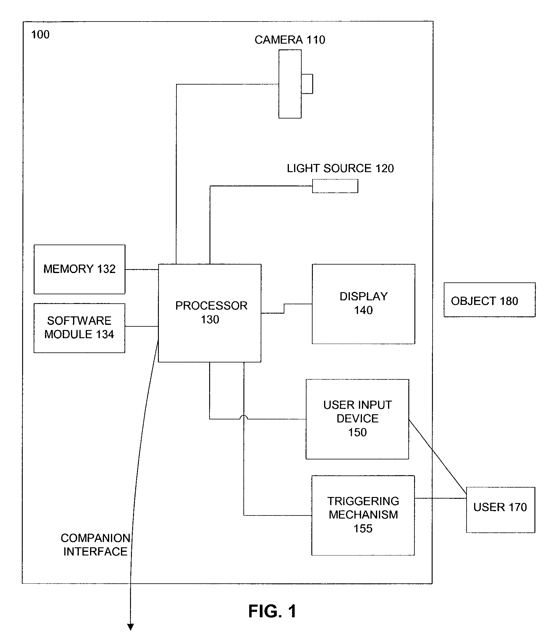
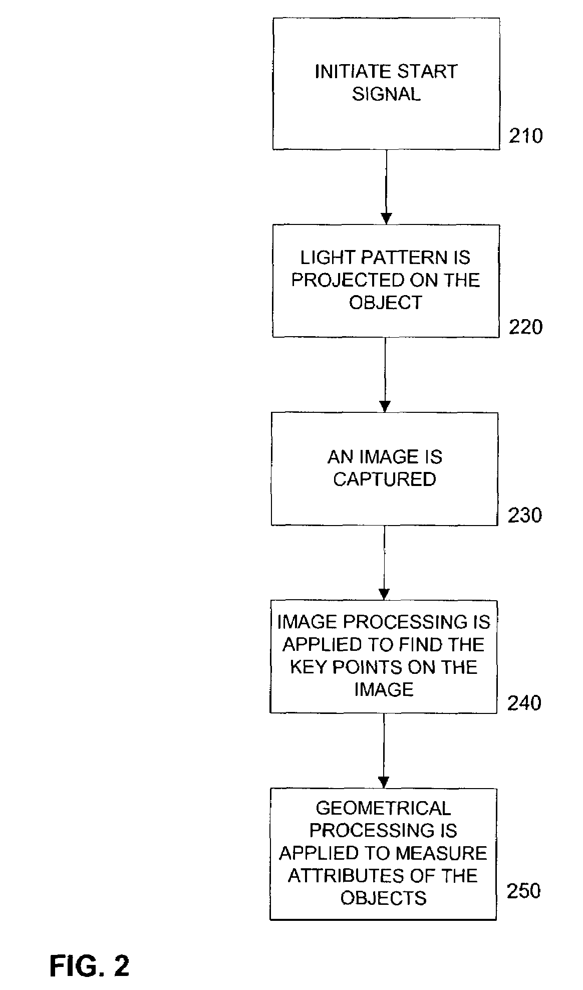
[0039]Embodiments of the invention describe a method and apparatus for measuring objects remotely. In the following description, for the purposes of explanation, numerous specific details are set forth in order to provide a thorough understanding of the present invention. It will be apparent, however, that the present invention may be practiced without these specific details. In other instances, well-known structures and devices are shown in block diagram form in order to avoid unnecessarily obscuring the present invention.

A. Overview

[0040]According to embodiments of the invention, objects may be measured by optical measurement devices. Such devices project light sources on an object and estimate the real world lengths on the object from the images of the object. The lengths can be measured using a combination of apparatus, methods and algorithms such as described herein.

[0041]In an embodiment, one type of an optical measurement device, called “an optical ruler” is described. Optica...


PUM


Abstract

A class of measurement devices can be made available using a family of projection patterns and image processing and computer vision algorithms. The proposed system involves a camera system, one or more structured light source, or a special pattern that is already drawn on the object under measurement. The camera system uses computer vision and image processing techniques to measure the real length of the projected pattern. The method can be extended to measure the volumes of boxes, or angles on planar surfaces.

Description

RELATED APPLICATION AND PRIORITY INFORMATION This application claims benefit of priority to:[0001]Provisional U.S. Patent Application No. 60 / 371,752, entitled “Vision Based Virtual Ruler,” naming Salih Burak Gokturk as inventor, filed on Apr. 10, 2002;[0002]Provisional U.S. Patent Application No. 60 / 429,750, entitled “Algorithms and Design Alternatives for Virtual Ruler,” naming Salih Burak Gokturk as inventor, filed on Nov. 27, 2002;[0003]Provisional U.S. Patent Application No. 60 / 420,217, “Method and Apparatus for measuring boxes,” naming Carlo Tomasi as inventor, filed on Oct. 21, 2002;[0004]Provisional U.S. Patent Application No. 60 / 426,760, “More Methods and Apparatus for measuring everyday common objects,” naming Fahri Surucu as inventor, filed on Nov. 15, 2002;[0005]Provisional U.S. Patent Application No. 60 / 433,144, “Ser. No. 60 / 433,144, “Algorithms and Methodologies for Box Volume Measurement Device,” naming Salih Burak Gokturk as inventor, filed on Dec. 13, 2002.[0006]All ...

Claims


Application Information

Patent Timeline
IPC IPC(8): G06K9/00G01B11/25
CPCG01B11/2509G06T7/0057G01B11/2545G06T7/521
Inventor GOKTURK, SALIH BURAKTOMASI, CARLOSURUCU, FAHRI
Owner MICROSOFT TECH LICENSING LLC
Why Eureka
Try Eureka