AI technical title is built by Patsnap AI team. It summarizes the technical point description of the patent document.
a technology for orthopaedic devices and supports, applied in the field of orthopaedic supports, can solve the problems of large labor costs, large thickness of stays, and limited shape of stays,
Inactive Publication Date: 2007-12-25
OSSUR HF
View PDF28 Cites 123 Cited by
Summary
Abstract
Description
Claims
Application Information
AI Technical Summary
This helps you quickly interpret patents by identifying the three key elements:
Problems solved by technology
Method used
Benefits of technology
Benefits of technology
[0010]The object of the present invention is to advance the art with respect to orthopedic supports and to provide an improved method for manufacturing orthopedic supports.
Problems solved by technology
A drawback of these designs is that they require a great deal of labor to construct.
A further drawback is that the stays are typically die-cut from plastic of constant thickness.
The shape of the stays is therefore quite limited, and the final support often does not fit the anatomy perfectly.
While stays can be manufactured to have a particular contour, the manufacturing process is not simple and is often fairly expensive.
The end result is a shoe with plastic on both the outside and the inside, and the shoe provides no cushioning between the molded plastic and the foot.
Method used
Image
Click on the blue label to locate the original text in one second.
Reading with bidirectional positioning of images and text.
Examples
Embodiment Construction
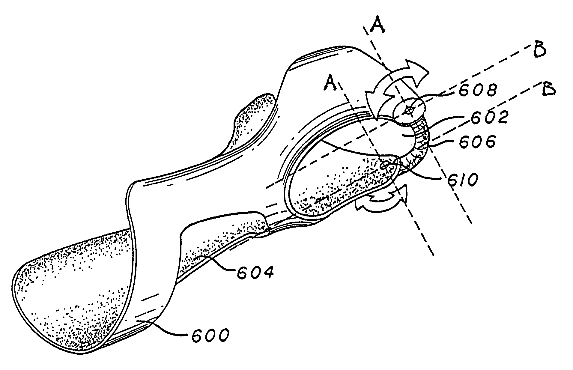
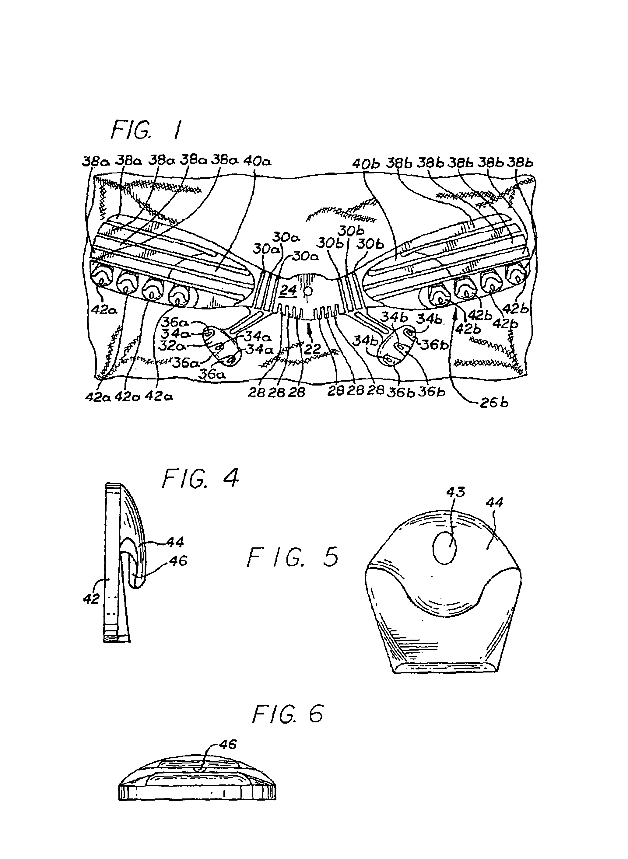
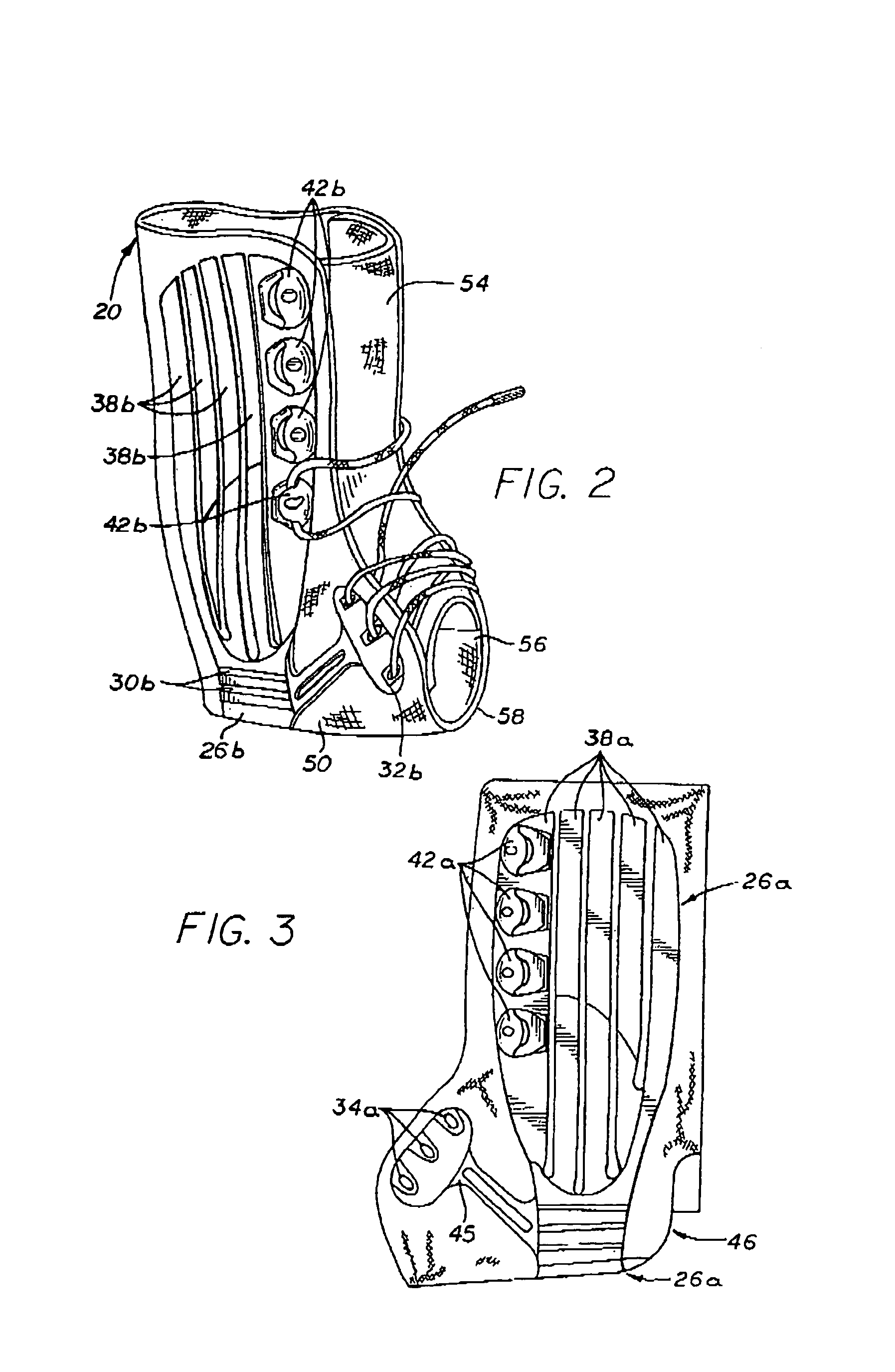
[0063]FIG. 1 illustrates a sheet of flexible porous sheet material 20 onto which a semi-rigid plastic exo-structure 22 has been injection molded. To form the exo-structure 22, the sheet material 20 is stretched across an injection mold, which is then closed under normal hydraulic pressure. The edges of the sheet material 20 normally extend beyond the cavity of the mold (not shown). Once the mold is hydraulically closed, the injection molding mechanism injects melted plastic into the mold to form the exo-structure 22. The melted plastic permeates the porous sheet material 20 and bonds to the sheet material 20 when it cools. Consequently, no additional securing means is necessary to attach the exo-structure 22 to the sheet material 20.
[0064]A variety of different materials may be used for both the sheet material 20 and the injection-molded exo-structure 22. For purposes of illustration but not limitation, the sheet material should be a material that is both suitable for use in an orth...
PUM
Abstract
The present invention pertains to an orthopedic support having a flexible inner member and an exo-skeleton that is molded directly onto the flexible inner member. One aspect of the invention relates to a wrist support having a thumb spica. The wrist support includes a molded plastic exostructure supplying support for resisting motion of said wrist. An inner fabric support is attached to said molded exostructure for providing cushioning to the wrist area. A separate, attachable thumb spica member is provided for optionally configuring the wrist support to include a thumb spica. Other embodiments include an orthopedic support having an attachable stay; a web bridge that extends across and supports the web of the hand; an adjustable wrist support having an adjustable forearm portion that can accommodate various sizes of forearms; a wrist brace having a space to accommodate the web of the hand; and a support having an interior padding member, with the padding member itself having a support structure molded onto the padding. Another aspect of the invention relates to a method of molding the exostructure onto a central core that is placed inside a mold.
Description
I. RELATED APPLICATIONS[0001]This application is a continuation-in-part of parent application Ser. No. 09 / 504,980, filed Feb. 15, 2000, now abandoned, which is a continuation-in-part of Ser. No. 09 / 018,318, filed Feb. 3, 1998, now U.S. Pat. No. 6,024,712, which is a continuation-in-part of Ser. No. 08 / 580,129 filed Dec. 28, 1995, now U.S. Pat. No. 5,713,837, all of whose contents are hereby incorporated by reference.II. BACKGROUND OF THE INVENTION[0002]A. Field of the Invention[0003]The present invention relates to orthopedic supports and, more particularly, to an orthopedic support that has a molded exo-structure.[0004]B. Prior Art[0005]There are a number of known ways to stiffen fabric orthopedic supports for injured parts of the anatomy. U.S. Pat. No. 4,724,847, for example, discloses an ankle brace that has a plurality of pockets. Rigid stay members are inserted into the pockets to form a rigid structure that surrounds and immobilizes the ankle. U.S. Pat. Nos. 3,298,365, 4,280,4...
Claims
Application Information
Patent Timeline
Application Date:The date an application was filed.
Publication Date:The date a patent or application was officially published.
First Publication Date:The earliest publication date of a patent with the same application number.
Issue Date:Publication date of the patent grant document.
PCT Entry Date:The Entry date of PCT National Phase.
Estimated Expiry Date:The statutory expiry date of a patent right according to the Patent Law, and it is the longest term of protection that the patent right can achieve without the termination of the patent right due to other reasons(Term extension factor has been taken into account ).
Invalid Date:Actual expiry date is based on effective date or publication date of legal transaction data of invalid patent.
Patent Type & AuthorityPatents(United States)
IPC IPC(8): A61F5/00A61F5/01
CPCA61F5/0118A61F5/0111
InventorIGLESIAS, JOSEPH M.GRIM, TRACY E.WYATT, STACYPELOTE, STEVETERAN, LUIS F.

