Spinal three-dimensional orthopedic equipment

a three-dimensional, orthopedic technology, applied in the field of spinal three-dimensional orthopedic equipment, can solve the problems of high cost of operation, inability to effectively treat these diseases, limited application scope of operation, etc., and achieve the effect of convenient operation and better curative

Inactive Publication Date: 2001-12-11
ZHANG JI LING
View PDF12 Cites 22 Cited by
  • Summary
  • Abstract
  • Description
  • Claims
  • Application Information

AI Technical Summary

Benefits of technology

The object of the present invention is to further improve the Chinese Patent CN2064643U "Multi-functional Draught Bed", and to provide a three-dimensional ...

Problems solved by technology

Medication is not efficacious to these diseases.
In addition, the cost of operation is high, while the patient has to endure the long operation and tremendous suffering thereafter.
Therefore, the applicable scope of operation is limited.
However, all the existing traction apparatus adopts linear traction, only in one direction.
Since it not can remedy the angular displacement between the vertebras, the curative effect is not ideal.
Further, the process of draught is usually performed by manual labor, or by hydraulic or mechanical transmission, and the draught velocity is low, and the patient may feel uncomfortable in the process of draught, which has an adverse effect on the treatment.
In addition, trauma would be caused when the distance of draught exceeds the limit because of misoperation.
This makes the patient suffer from pain in the neck, shoulders, waist an...

Method used


Image

  • Spinal three-dimensional orthopedic equipment
  • Spinal three-dimensional orthopedic equipment
  • Spinal three-dimensional orthopedic equipment

Examples


Embodiment Construction

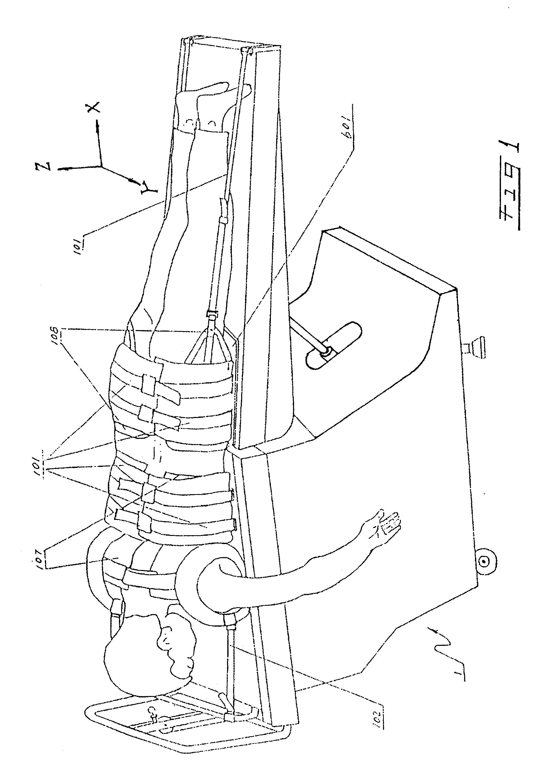
The preferred embodiment of the present invention will be described with reference to the drawings. It should be understood that the embodiment is only to illustrate the invention, not to limit its scope. The scope of protection of the invention should be defined by the appended claims.

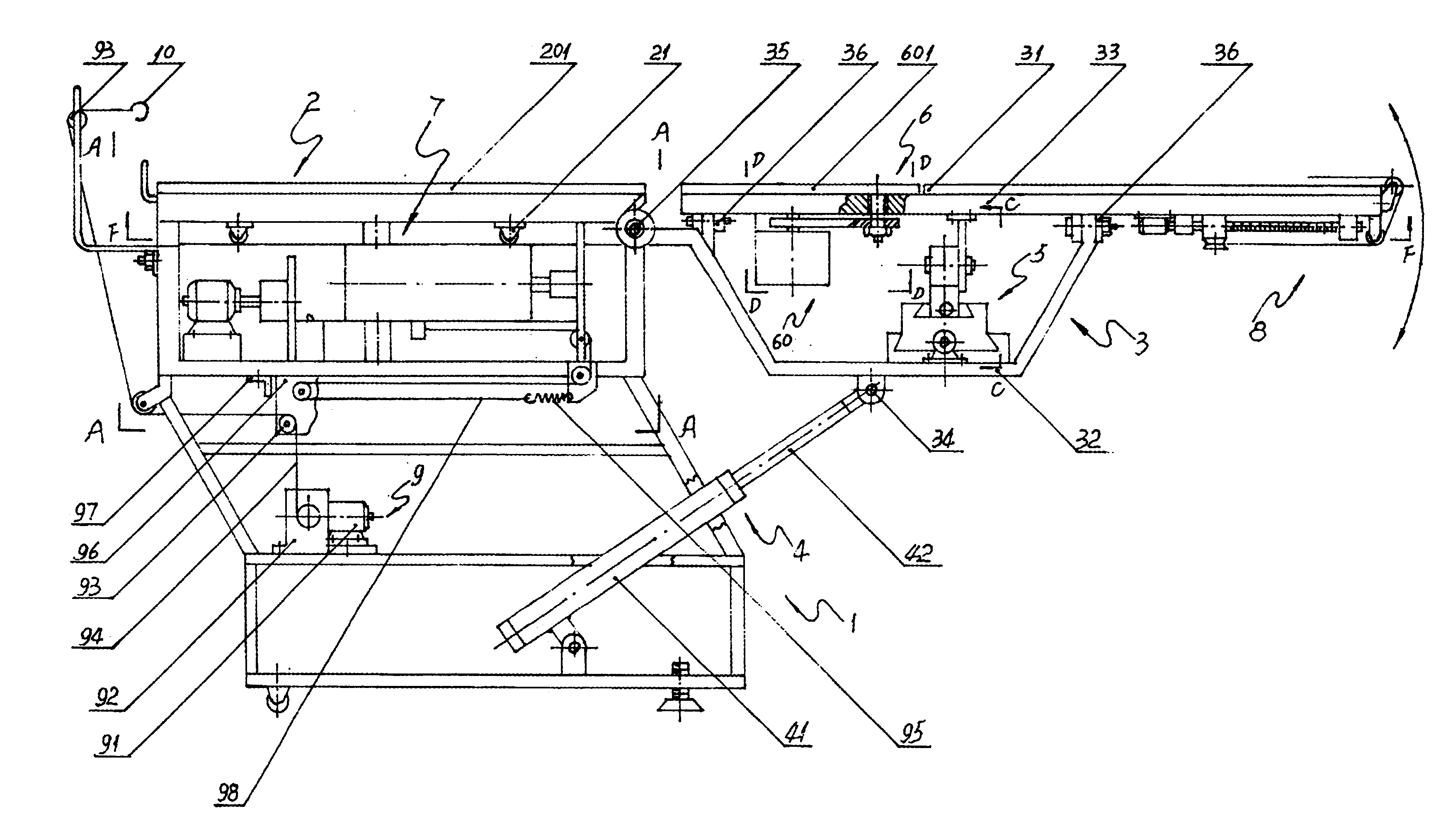
FIG. 1 is a perspective view of an embodiment of the three-dimensional spine remedying apparatus of the present invention. In FIG. 1, reference number 1 denotes the case-shaped frame on which all the components of the apparatus are mounted. The electric control device (not shown) of the apparatus may be arranged on either side of the frame. As shown in FIG. 1, the patient lying face down on the apparatus is being treated.

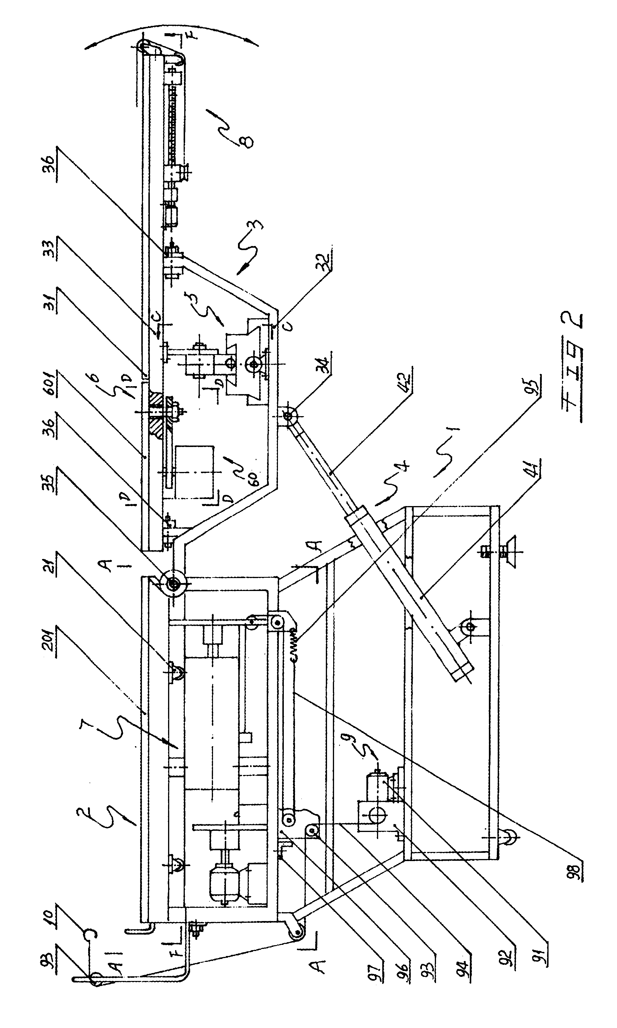
Now referring to FIG. 2, the cephalothoracic board device 2 is arranged on the frame 1, wherein the cephalothoracic board 201 is supported by four wheels 21, which move along the rails on the frame 1. The magnetic driving device 7 for moving the cephalothoracic board device 2 horizont...


PUM


Abstract

The object of the present invention is to provide a three-dimensional spine remedying apparatus, which offers more comprehensive functions and better curative effects, and frees the patient from discomfort during the process of treatment. The apparatus of the invention includes: a frame; a cephalothoracic board and a driving device thereof; a hip-leg board and a driving device thereof; a low-speed draught device; a hip board capable of rotating around the axle Z and a driving device thereof; a device for securing the body of the patient and an adjusting means thereof. The driving devices of said cephalothoracic board, hip-leg board and hip board are high-speed driving devices employing electromagnetic force. Said hip-leg board and hip board are capable of not only rotating by a predetermined angle, but also making high-speed angular oscillation. In addition, in said driving device of said cephalothoracic board, a clutch is provided for linking up the high-speed movement of the magnetic driving device of the cephalothoracic board with the low-speed movement of the said draught device.

Description

The present invention relates to medical appliances for treating parenchyma trauma between vertebras and, in particular, to a therapeutic apparatus for remedying three-dimensional displacements between vertebras.Diseases with parenchyma trauma between vertebras, such as prolapse of lumbar intervertebral disc, cervical spondylopathy and thoraxlumbar rear joint disorder, are familiar diseases which bring tremendous suffering to the patient. Medication is not efficacious to these diseases. In addition, the cost of operation is high, while the patient has to endure the long operation and tremendous suffering thereafter. Therefore, the applicable scope of operation is limited.Remedying apparatus for treating these diseases have been widely used. For example, many types of traction apparatus have been developed. However, all the existing traction apparatus adopts linear traction, only in one direction. Since it not can remedy the angular displacement between the vertebras, the curative ef...

Claims


Application Information

Patent Timeline
IPC IPC(8): A61H1/02A61F5/058A61F5/042
CPCA61H1/0222A61H1/0218A61H1/0244A61H2001/0203A61H2001/0233A61H2201/1621A61H2201/163
Inventor ZHANG, JI LING
Owner ZHANG JI LING
Why Eureka
Try Eureka