
Fixation of orthopaedic devices

a technology for orthopaedic devices and fixation, which is applied in the direction of prosthesis, ligaments, impression caps, etc., can solve the problems of removing the implant, loosing the implant, and ultimately detaching the implant, etc., and may be required for revision surgery, removal of the implant, and removal of the implan

Inactive Publication Date: 2014-09-18
SMED TATD
View PDF1 Cites 17 Cited by
  • Summary
  • Abstract
  • Description
  • Claims
  • Application Information

AI Technical Summary

Benefits of technology

The present invention is an orthopaedic implant that can withstand natural pull out forces when implanted within a patient. This means that it can resist being pulled out of the patient's body without needing too much force to remove it. This provides a safer and more effective way to use orthopaedic implants in patients.

Problems solved by technology

These natural forces can cause the implant to either loosen from the implantation site or, worse, ultimately detach from the implant site.
One problem that arises with implanted devices is that there is a risk that a revision surgery, to remove the implant, may be required due to reasons such as an incorrect placement, an unforeseen event or an infection causing the implant to prematurely fail.
In such cases, removing the implant can be a traumatic event for anatomy structures around the site if a lot of force is required to loosen the implant and remove it.
A similar problem can occur with devices that are meant to be temporary, i.e., have a relatively short implantation period.
The device can become too integrated with the body and become very difficult to remove, which can lead to trauma at the implantation site during removal.

Method used


Image

  • Fixation of orthopaedic devices
  • Fixation of orthopaedic devices
  • Fixation of orthopaedic devices

Examples


Embodiment Construction

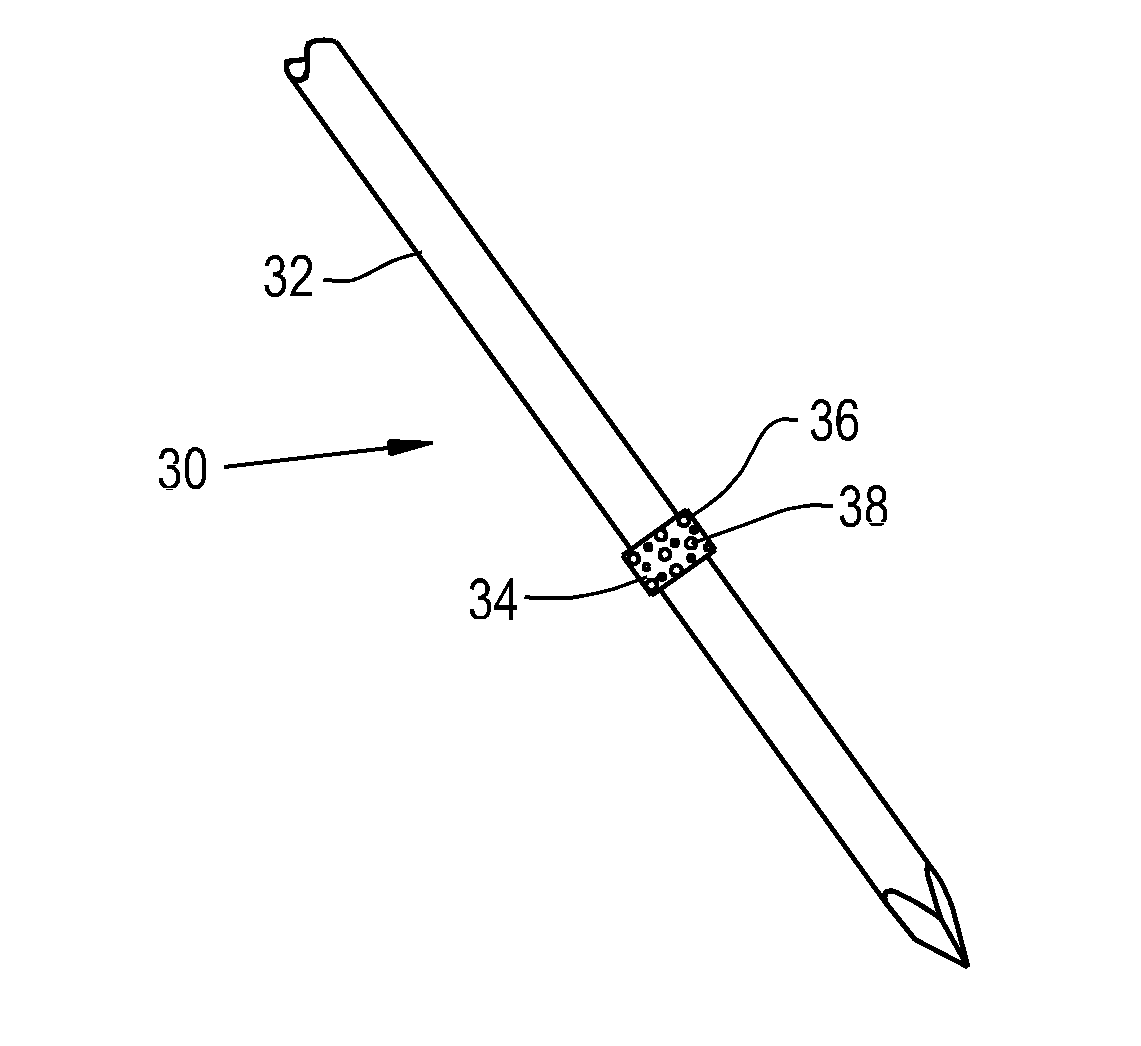
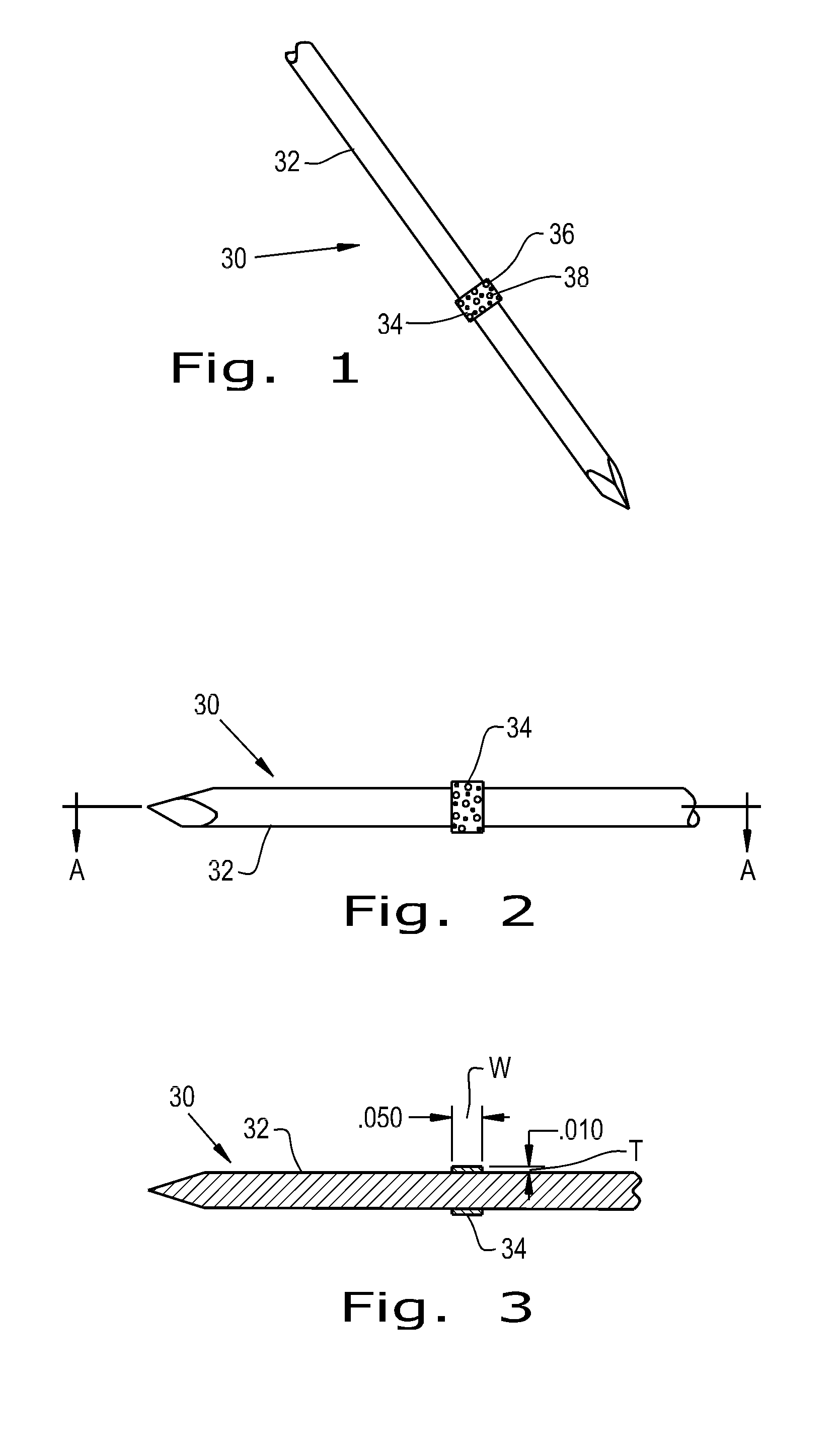
[0040]Referring now to the drawings, and more particularly to FIG. 1, there is shown an orthopaedic implant 30 which generally includes a base device 32 and a fixation material 34 attached to the base device 32. The base device 32 shown is a bone pin that can reside within a patient for a short period of time. The base device 32 can be constructed of metals commonly used in orthopaedic implants such as titanium, cobalt chrome and stainless steel. Alternatively, the base device can be constructed of biocompatible polymers such as polyether ether ketone (PEEK), polylactic acid (PLA), polyglycolic acid (PGA), polyethylene (PE) and blends thereof.

[0041]The fixation material 34 attached to the base device 32 is shaped as a thin band wrapped around the circumference of the base device 32. The fixation material 34 can be a porous polymer or metal that has a roughened surface 36 to provide immediate fixation of the device 30 due to frictional forces and to encourage quick tissue ingrowth in...


PUM

PropertyMeasurementUnit
diameteraaaaaaaaaa
adhesive forceaaaaaaaaaa
plurality of poresaaaaaaaaaa

Abstract

The present invention provides an orthopaedic implant including a base device having a device surface and a fixation material attached to at least one portion of the device surface. The fixation material is configured to provide a minimally sufficient adhesive force to resist natural pull out caused by forces acting on the base device after implantation and bone growth. Also provided is a method of manufacturing an orthopaedic implant. A base device with a device surface is provided and a minimally sufficient adhesive force, that can resist natural pull out caused by forces acting on the base device after implantation and bone growth, is determined. A proper amount of fixation material sufficient to provide an adhesive force equal to the minimally sufficient adhesive force is determined and fixation material is applied to the device. When the proper amount of fixation material is applied to the device surface, application is stopped.

Description

CROSS REFERENCE TO RELATED APPLICATIONS[0001]This is a non-provisional application based upon U.S. provisional patent application Ser. No. 61 / 787,507, entitled “FIXATION OF ORTHOPAEDIC DEVICES”, filed Mar. 15, 2013, which is incorporated herein by reference.BACKGROUND OF THE INVENTION[0002]1. Field of the Invention[0003]The present invention relates to orthopaedic devices, and more particularly, to orthopaedic implants.[0004]2. Description of the Related Art[0005]Orthopaedic implants are known that are implanted into the body to achieve various surgical objectives. Such implants include bone pins, bone screws and bone plates. The implantation period of the implant can vary from a short period, such as a couple of days, to the end of a patient's life. During the implantation period, the implant will experience natural forces caused by surrounding anatomy structures due to static and dynamic conditions of the anatomy structures. These natural forces can cause the implant to either loo...

Claims


Application Information

Patent Timeline
Patent Type & Authority Applications(United States)
IPC IPC(8): A61L31/14A61L31/04A61L31/08A61L31/16
CPCA61L31/146A61L31/16A61L31/088A61L31/04A61L31/022A61L31/06A61L2300/404A61L2300/41A61L2300/414A61L2400/18A61B17/7098A61B17/8028A61B17/846A61B17/8625A61B2017/8655C08L71/00
Inventor STALCUP, GREGORY C.KNAPP, TROY D.JURICK, JOSEPH W.NEBOSKY, PAUL S.WILLIAMS, KREIGH R.
Owner SMED TATD
Learn More