Ankle foot orthopaedic devices

an orthopaedic device and hind foot technology, applied in the field of ankle foot orthopaedic devices, can solve the problems of complex anatomical correct motion of the hind foo

Active Publication Date: 2013-08-29
C PRO DIRECT
View PDF22 Cites 23 Cited by
  • Summary
  • Abstract
  • Description
  • Claims
  • Application Information

AI Technical Summary

Benefits of technology

[0017]This invention overcomes fundamental limitations of current bracing solutions and makes new improved therapies possible for people affected by a myriad of disabling conditions of the foot. The inventor has precisely understood the dominant anatomical motions of both tibio-talar and sub-talar joints and realised how to model these in a single wearable device. Of particular significance is the inventor's realisation of the significance of the surprising nature of the sub-talar joint. The invention exploits the geometry of this motion to create a dynamic orthopaedic device that can brace or bias the sub-talar joint without the need for connecting bars or a fixed and bent knee.
[0025]The device is able to brace or bias the user's foot in a position of abduction or adduction through the axis of rotation of the sub-talar joint without the need for either a connecting bar between each leg or a leg engaging item that extends above the knee joint of the leg and which requires the leg to be held in a fixed position substantially bent at the knee.
[0045]According to a third aspect of the present invention, there is provided a method of bracing a lower leg relative to a foot such that a connecting bar between the lower limbs is not required, a leg engaging item does not need to extend above the user's knee, or the user's leg does not need to be held in a bent position, the method including providing an ankle foot orthopaedic device according to any of the preceding statements.

Problems solved by technology

Anatomically correct motion of the hind foot is complex as it involves motions that are the combined motions of the motions of the tibio-talar and sub-talar joints.

Method used


Image

  • Ankle foot orthopaedic devices
  • Ankle foot orthopaedic devices
  • Ankle foot orthopaedic devices

Examples


first embodiment

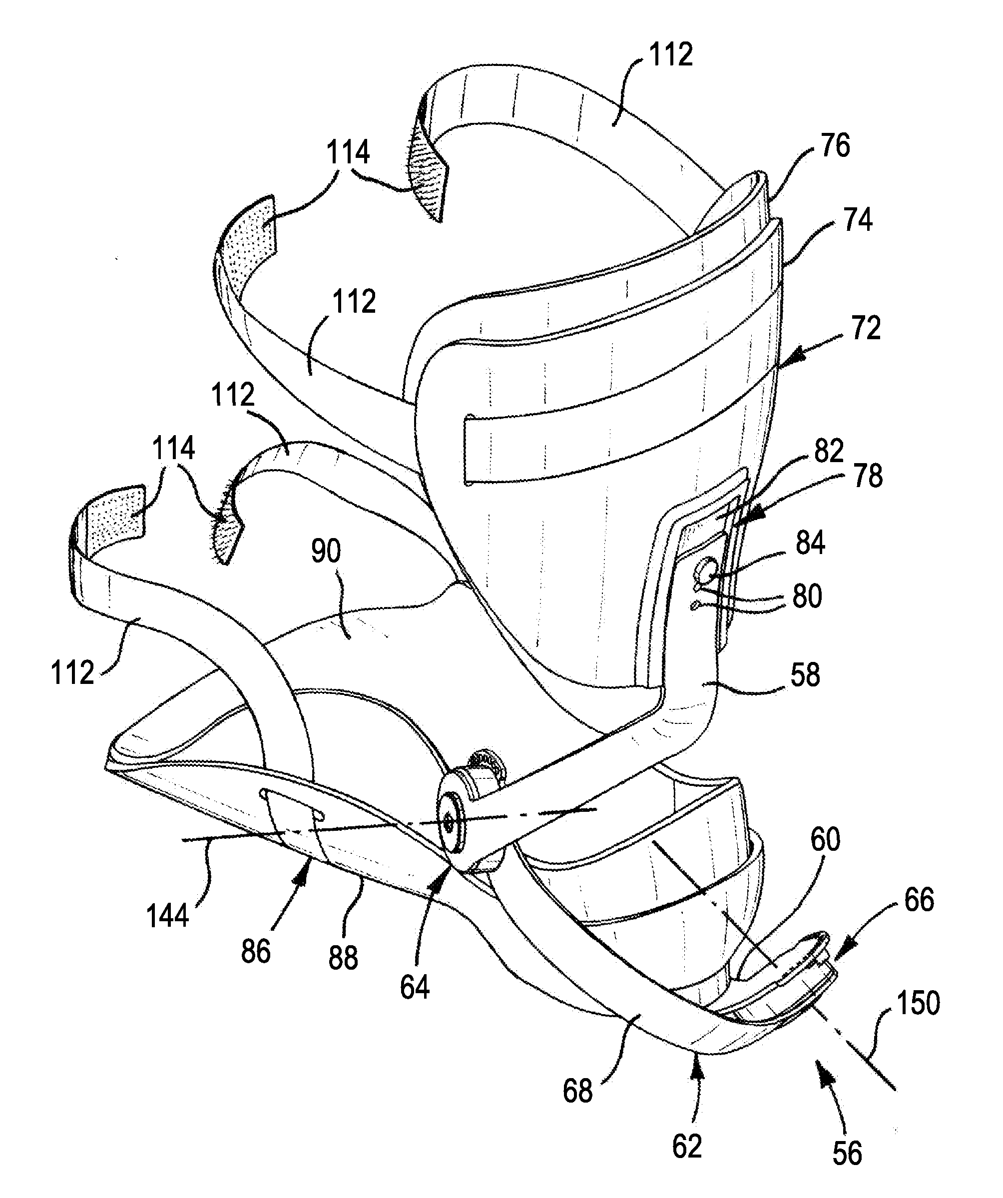
[0130]FIGS. 13 and 14 show a third orthopaedic device 356 including a leg engaging item 72, a first connecting arm 58 for association with a leg engaging item 72, and a shoe engaging item 60 for association with a first connecting arm 58 and shoe 86. This device has just one adjuster 66 which corresponds to the first adjuster 66 of the The third orthopaedic device 356 thus permits adjustment movement only about the first device axis of rotation 150, which in use in the fitted condition corresponds to the sub-talar pivot axis 50. This device 356 could be used, for example, in cases where therapy involving only movement of the foot 14 about the sub-talar pivot axis 50 is required.

[0131]Similarly, in other embodiments not shown, a device of the invention could comprise just one adjuster corresponding to the second adjuster 64 of the first embodiment.

[0132]FIGS. 17 and 18 show a fourth orthopaedic device 556 including a leg engaging item 572, a first connecting arm 58 for association w...

embodiment 56

[0139]In this example, the device 756 is similar to the first device embodiment 56 except that the second connecting arm 68 extends outwardly laterally from the first adjuster 66 to the second adjuster 64, which is in a lateral position. In this position, advantageously, walking could be easier for the user as the first adjusters 64 of the two devices 756 on the two lower limbs do not dash or obstruct.

[0140]FIG. 22 shows a seventh orthopaedic device 856 including a leg engaging item 72, a first connecting arm 58 for association with a leg engaging item 72 and a second connecting arm 68, a second connecting arm 68 for association with a first connecting arm 58 and a shoe engaging item 60 (not shown in FIG. 22) and three spaced adjusters 64, 66, comprising a pair of second adjusters 64 which, in the adjustment condition, permits a second rotational adjustment movement around a second device axis of rotation 144 of the first connecting arm 58 relative to the second connecting arm 68 an...


PUM


Abstract

An ankle foot orthopaedic device (56) includes a first part (58) for association with a leg engaging item (72), a second part (60) for association with a foot engaging item (86) and a connector (62) for connecting the first part (58) to the second part (60). The connector (62) includes a first adjuster (66), which, in an adjustment condition, permits a first adjustment relative movement of the first part (58) and the second part (60) around a first device axis (150) of rotation. The connector (62) includes a second adjuster (64), which, in an adjustment condition, permits a second adjustment relative movement of the first part (58) and the second part (60) around a second device axis (144) of rotation. In use in a fitted condition in which the device (56) is fitted to a user's leg and foot, the first device axis (150) substantially corresponds with a dominant anatomical axis (50) of rotation of the sub talar joint and the second device axis (144) substantially corresponds with a dominant anatomical axis (44) of rotation of the tibio-talar joint.

Description

BACKGROUND OF THE INVENTION[0001]1. Field of the Invention[0002]The present invention relates to ankle foot orthopaedic devices.[0003]2. The Prior Art[0004]The dominant motion of the foot relative to the lower leg as required for walking and running occur through what is commonly described as the ankle joint. The ankle joint comprises two major joints each with a dominant axis of motion. The joint formed between the lower surface of the tibia and upper surface of the talus is known as the tibio-talar joint. The tibio-talar joint enables the foot to be raised and lowered or dorsiflexed and plantaflexed using medical terminology. The joint formed by the lower surface of the talus and the upper surface of the calcaneous enables the foot to be turned outwards or inwards in a rolling motion known as eversion and inversion. Anatomically correct motion of the hind foot is complex as it involves motions that are the combined motions of the motions of the tibio-talar and sub-talar joints.[00...

Claims


Application Information

Patent Timeline
Patent Type & Authority Applications(United States)
IPC IPC(8): A61F5/01
CPCA61F5/0127A61F5/0111A61F2005/0162A61F2005/0167
Inventor MORRIS, PHILIP GEORGE LITTLEAVON
Owner C PRO DIRECT
Why Eureka
Try Eureka