
Integrated thin film explosive micro-detonator

a micro-detonator and integrated technology, applied in the direction of fuse connectors, weapons, fuses, etc., can solve the problems of high electrical power and moderate electrical energies, inability to practicably and economically employ conventional detonator fabrication techniques, and inability to use electrically driven slapper devices

Inactive Publication Date: 2008-01-29
NAVY THE US SEC
View PDF8 Cites 15 Cited by
  • Summary
  • Abstract
  • Description
  • Claims
  • Application Information

AI Technical Summary

Benefits of technology

[0007]The present invention provides a method for making useful (detonating and non-detonating) explosive and ignition trains for incorporation into MEMS safety-and-arming devices. An important characteristic of the inventive explosive device is that it is capable of being initiated by

Problems solved by technology

MEMS safety-and-arming devices currently being conceived and developed require detonating sources of a size such that conventional detonator fabrication techniques cannot be practically and economically employed.
Such electrically driven slapper devices, while sufficiently small to be fabricated within a MEMS device, require high electrical power and moderate electrical energies.
Such slapper devices are relatively complex and expensive to fabricate making them inappropriate for low-energy, low-cost, high-volume MEMS applications, or MEMS applications where little or no onboard electrical energy is available.

Method used


Image

  • Integrated thin film explosive micro-detonator
  • Integrated thin film explosive micro-detonator
  • Integrated thin film explosive micro-detonator

Examples


Embodiment Construction

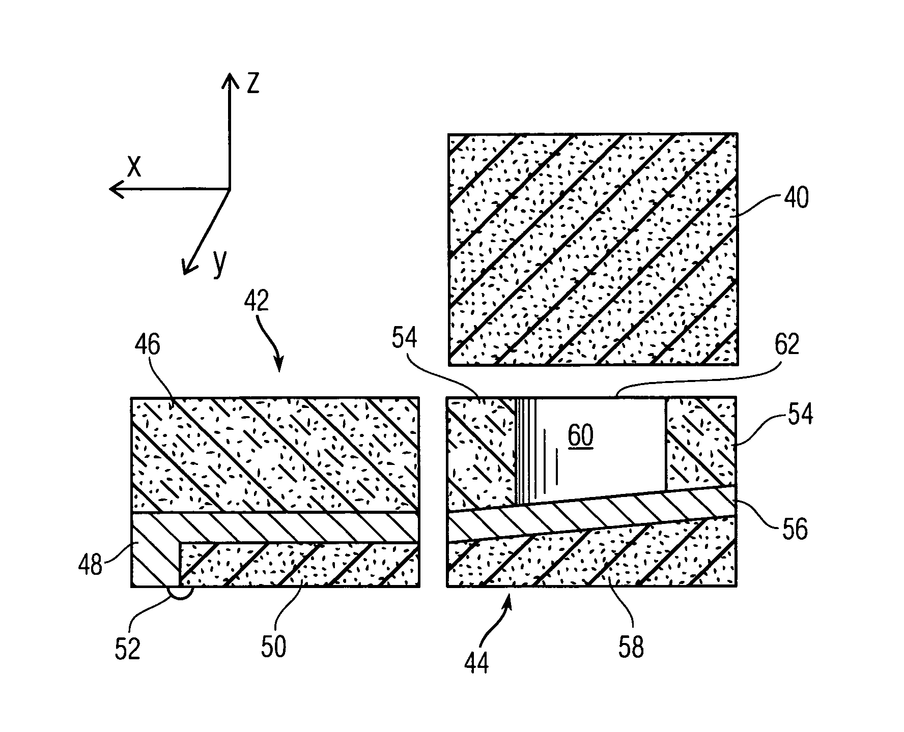
[0019]The present invention integrates fabrication of a micro-detonator in a monolithic MEMS structure using “in-situ” production of the explosive material within the device, in sizes with linear dimensions below about 1 mm. The invention is applicable to high-volume low-cost manufacturing of MEMS safety-and-arming devices. The inventive device can be initiated either electrically or mechanically at either a single point or multiple points, using energies of less than about 1 mJ.

[0020]The present invention reduces the use of toxic primary explosive materials, their starting materials, and detonation products (typically heavy metal salts) by nearly two orders of magnitude over currently employed macro-sized explosive trains. The invention thereby confers significant environmental advantages and assists in fulfilling Executive Order 12856, which mandates significant reductions in the use of environmentally toxic energetic materials. Toxic waste generation is concomitantly reduced.

[002...


PUM


Abstract

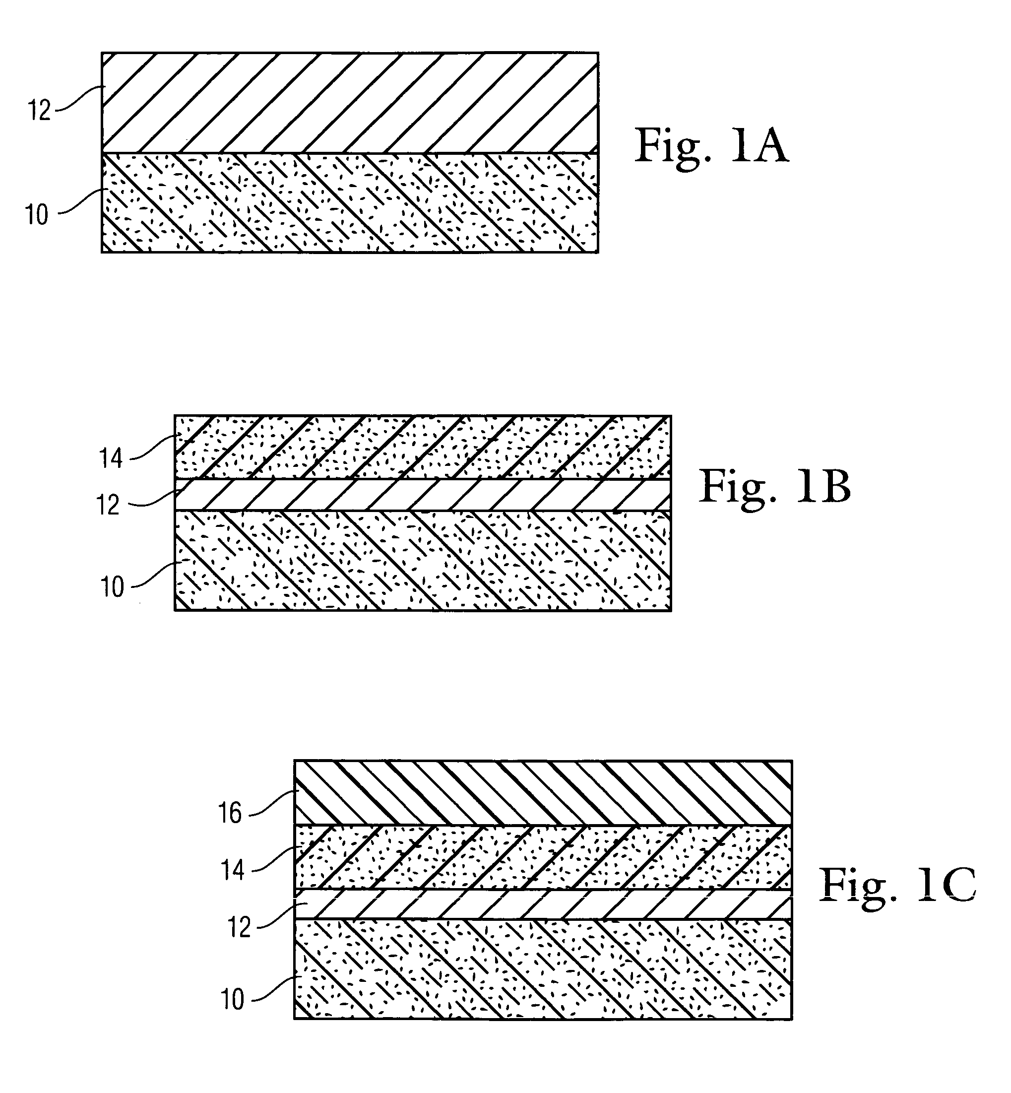
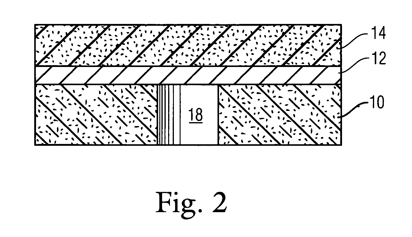
A method of making a thin film explosive detonator includes forming a substrate layer; depositing a metal layer in situ on the substrate layer; and reacting the metal layer to form a primary explosive layer. The method and apparatus formed thereby integrates fabrication of a micro-detonator in a monolithic MEMS structure using “in-situ” production of the explosive material within the apparatus, in sizes with linear dimensions below about 1 mm. The method is applicable to high-volume low-cost manufacturing of MEMS safety-and-arming devices. The apparatus can be initiated either electrically or mechanically at either a single point or multiple points, using energies of less than about 1 mJ.

Description

[0001]The present Application is a Divisional Application of U.S. patent application Ser. No. 10 / 729,266 filed on Dec. 3, 2003.STATEMENT OF GOVERNMENT INTEREST[0002]The invention described herein may be manufactured and used by or for the Government of the United States of America for government purposes without the payment of any royalties therefor.BACKGROUND OF THE INVENTION[0003]The invention relates in general to explosive and ignition trains for safety-and-arming devices and in particular to explosive and ignition trains for use with microelectromechanical systems (MEMS) safety-and-arming devices.[0004]MEMS safety-and-arming devices currently being conceived and developed require detonating sources of a size such that conventional detonator fabrication techniques cannot be practically and economically employed. The detonating sources for state of the art MEMS safety-and-arming devices preferentially employ a maximum size of one cubic millimeter (mm). By comparison, the smallest...

Claims


Application Information

Patent Timeline
IPC IPC(8): F42C15/184
CPCF42C15/184
Inventor LAIB, GERALD
Owner NAVY THE US SEC
Learn More