Non-volatile memory with redundancy data buffered in remote buffer circuits

a buffer circuit and non-volatile technology, applied in digital storage, building locks, instruments, etc., can solve the problem of not being able to use any odd redundant columns, and achieve the effect of reducing the number of redundant storage space and maximizing the utilization of redundant storage spa

Active Publication Date: 2008-01-29
SANDISK TECH LLC
View PDF37 Cites 51 Cited by
  • Summary
  • Abstract
  • Description
  • Claims
  • Application Information

AI Technical Summary

Benefits of technology

[0014]In another embodiment, the address granularity of the redundant data buffer circuits need not be the same as that of the column circuits. Preferably, the unit of address has a finer resolution than that of a column. A sub-column decoder further decodes the column address and a column offset address into sub-column addresses. This has the advantage of more efficient utilization of the redundant storage space since a single defective bit line can be replaced by another redundant bit line and not necessarily by a redundant column containing multiple bit lines.
[0015]The implementation of a remote buffer allows all redundant data that are normally tied to their respective redundant data latches to be free from the access restriction due to their location and memory architecture. For example, a set of even column circuits can only access even columns and therefore not be able to use any odd redundant columns, similarly for odd column circuits. The present scheme allows all the redundant data to be buffered in a central location that can be accessible by any number of column circuits regardless of their relative locations.

Problems solved by technology

For example, a set of even column circuits can only access even columns and therefore not be able to use any odd redundant columns, similarly for odd column circuits.

Method used


Image

  • Non-volatile memory with redundancy data buffered in remote buffer circuits
  • Non-volatile memory with redundancy data buffered in remote buffer circuits
  • Non-volatile memory with redundancy data buffered in remote buffer circuits

Examples


Embodiment Construction

[0035]A preliminary description of a typical memory employing column redundancy is useful to distinguish from the present invention.

Conventional Localized Redundant Data Scheme

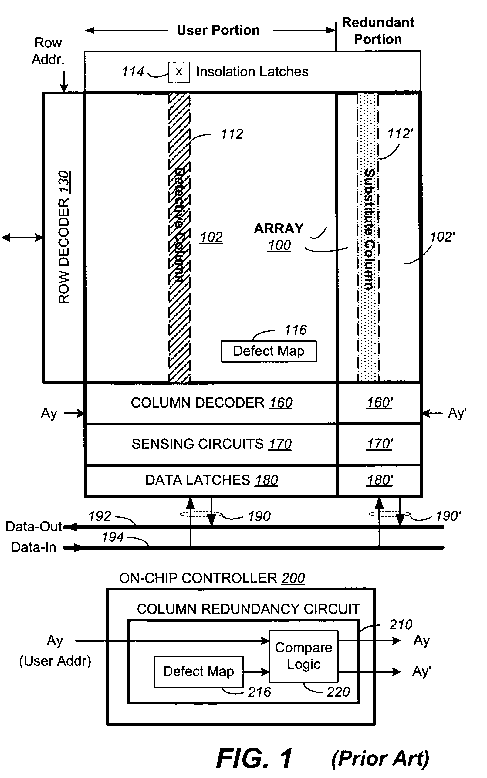
[0036]FIG. 1 illustrates a memory device with a conventional scheme of column redundancy in which redundant data is available only from the redundant portion. The memory device has an array of memory cells 100 which is partitioned into a user portion 102 and a redundant portion 102′. The memory cells in the array 100 are accessible by a set of word lines along a row and a set of bit lines along a column. The set of word lines is selectable by a row address via a row decoder 130. Similarly, the set of bit lines is selectable by a column address via a column decoder 160. Typically, a page of memory cells along a row is read or written together by a corresponding set of sensing circuits 170. A corresponding set of data latches 180 is used to latch the page of data that has been read from the memory or that are to...


PUM


Abstract

A memory has defective locations in its user portion replaceable by redundant locations in a redundant portion. Data latches in column circuits of user and redundant portions allow data sensed from or to be written to a memory to be exchanged with a data bus. A remote redundancy scheme has the redundant data available from a central buffer accessible by any number of column circuits. Redundant data buffer circuits enable bus exchange with data from the user data latches except for defective locations when data are taken from the central buffer. In this way only addressing for the user portion is used for bus exchange. Also, accessibility to the redundant data will not be restricted by the locations of the column circuits relative to the redundant data latches and the buffered redundant data can be accessed at a finer granularity than that imposed by the column circuits.

Description

CROSS REFERENCE TO RELATED APPLICATION[0001]This application is related to an application being filed concurrently herewith by the same inventor, entitled “Method for Remote Redundancy for Non-Volatile Memory”. This application is further related to two other applications being filed concurrently by Farookh Moogat et al., entitled “Method for Column Redundancy Using Data Latches in Solid-State Memories” and “Non-Volatile Memory With Redundancy Data Buffered in Data Latches for Defective Locations”. The cited applications are incorporated herein in their entirety by this reference.FIELD OF THE INVENTION[0002]This invention relates generally to non-volatile semiconductor memory such as electrically erasable programmable read-only memory (EEPROM) and flash EEPROM, and specifically ones implementing column redundancy features.BACKGROUND OF THE INVENTION[0003]Solid-state memory capable of nonvolatile storage of charge, particularly in the form of EEPROM and flash EEPROM packaged as a sma...

Claims


Application Information

Patent Timeline
Patent Type & Authority Patents(United States)
IPC IPC(8): G11C7/00G11C8/00
CPCG11C29/846G11C29/808Y10T70/7655
Inventor CERNEA, RAUL-ADRIAN
Owner SANDISK TECH LLC
Why Eureka
Try Eureka