
Image forming apparatus having developing device with sealing members and method of manufacture

Inactive Publication Date: 2008-01-29
SEIKO EPSON CORP
View PDF24 Cites 4 Cited by
  • Summary
  • Abstract
  • Description
  • Claims
  • Application Information

AI Technical Summary

Benefits of technology

[0026]The present invention has been made in light of the foregoing issues. It is an object of the present invention to achieve a developing device, an image forming apparatus, and an image forming system in which the abutting pressure of the sealing member against the developer bearing roller is made even. Another object of the present invention is to achieve a developing device, an image forming apparatus, and an image forming system that can be easily assembled. Another object of the present invention is to make a sealing member abut against a developer bearing roller appropriately. Another object of the present invention is to achieve a developing device that allows the abutting pressure of an end sealing member against a developer bearing roller to be set to a suitable value, and an image forming apparatus and an image forming system provided with such a developing device.
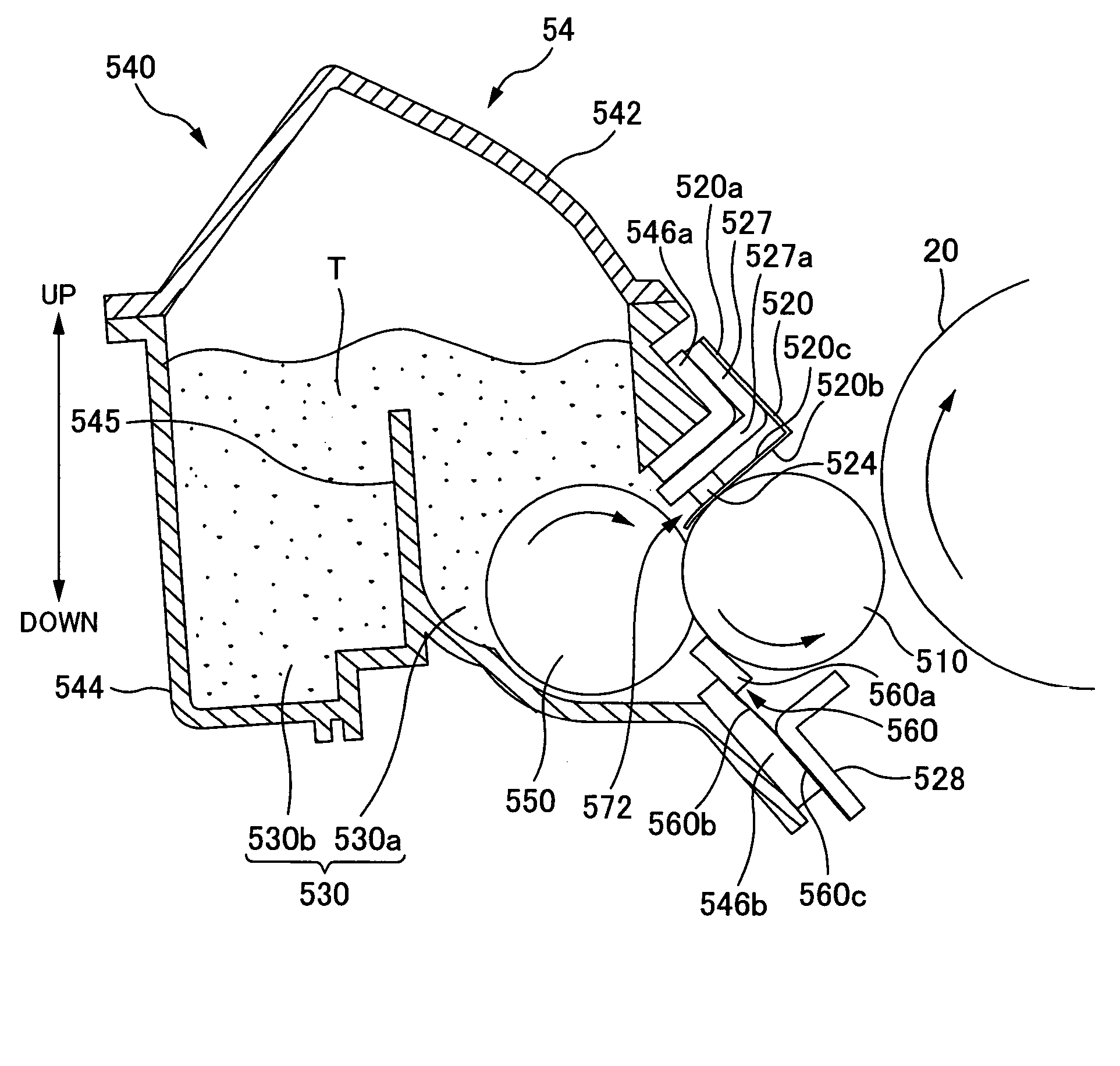
[0029]Another aspect of the present invention is a developing device for developing a latent image borne on an image bearing body using a developer borne on a developer bearing roller, the developing device comprising: a housing that is for containing the developer and that has an opening; the developer bearing roller that is for bearing the developer and that is provided facing the opening; and a sealing member for preventing the developer from spilling from the housing, wherein the sealing member is supported on a side of one end in a lateral direction thereof by the developing device in a bent state, wherein the sealing member abuts against the developer bearing roller on a side of an other end in the lateral direction thereof, and wherein a flexural rigidity of the sealing member on the side of one end in the lateral direction thereof is larger than a flexural rigidity of the sealing member on the side of the other end in the lateral direction thereof.
[0030]Another aspect of the present invention is a developing device comprising: a housing that is for containing a developer and that has an opening; a developer bearing roller that is for bearing the developer and that is provided facing the opening; and an end sealing member that is provided between the housing and the developer bearing roller and that is for preventing the developer from spilling from an end of the developer bearing roller, wherein a section of the housing that is in opposition to the end sealing member is provided with a cut-out section.

Problems solved by technology

Therefore, in such a developing device, there are problems in that it is difficult to carry out appropriate positioning of the relative position of the urging member with respect to the developing roller, the sealing member, and the housing, and thus, it is difficult to make the abutting pressure of the sealing member against the developing roller even.
Such tasks are extremely burdensome.
In a situation in which the sealing member is supported in a bent state on the side of one end in the lateral direction thereof by the developing device and in which the sealing member abuts against the developer bearing roller on the side of the other end in the lateral direction thereof, the abutment of the sealing member against the developer bearing roller may become inappropriate due to how the sealing member bends.
Examples in which the abutment becomes inappropriate are cases where the lateral-direction width of abutment of the sealing member is too short, or where the abutting pressure of the sealing member is uneven.
Such an inappropriate abutment may cause deterioration in the function of the sealing member of preventing the developer from spilling.
This is because the function of preventing the developer from spilling becomes insufficient if the abutting pressure is small, whereas the torque required for rotating the developer bearing roller becomes large if the abutting pressure is large.
In some cases, however, it is not possible to apply an abutting pressure of a suitable value, depending on the relationship between the width of the end sealing member and the width of a sealing space between the housing and the developer bearing roller where the end sealing member is provided.

Method used


Image

  • Image forming apparatus having developing device with sealing members and method of manufacture
  • Image forming apparatus having developing device with sealing members and method of manufacture
  • Image forming apparatus having developing device with sealing members and method of manufacture

Examples


first through third embodiments

Overall Configuration Example of Image Forming Apparatus

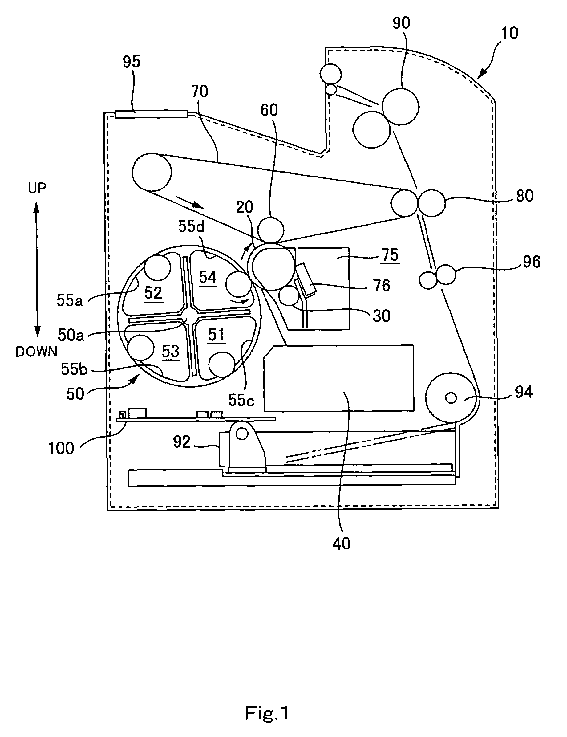
[0191]Next, with reference to FIG. 1, an outline of an image forming apparatus will be described, taking a laser-beam printer 10 (hereinafter referred to also as “printer”) as an example. FIG. 1 is a diagram showing main structural components constructing the printer 10. It should be noted that in FIG. 1, the vertical direction is shown by the arrow, and, for example, a paper supply tray 92 is arranged at a lower section of the printer 10, and a fusing unit 90 is arranged at an upper section of the printer 10.

[0192]As shown in FIG. 1, the printer 10 according to the present embodiment is provided with a charging unit 30, an exposing unit 40, a YMCK developing unit 50, a first transferring unit 60, an intermediate transferring body 70, and a cleaning unit 75. These components are arranged in the direction of rotation of a photoconductor 20, which serves as an example of an image bearing body. The printer 10 is further provided w...

first embodiment

(1) Other Considerations Regarding First Embodiment

[0254]In the foregoing embodiment, an upper sealing member 520 arranged such that its longitudinal direction is in an axial direction of the developing roller 510 was described as an example of a sealing member. This, however, is not a limitation. The present invention is applicable to any type of sealing member that is supported by a holder 526 and that abuts against the developing roller 510 to prevent the toner T from spilling.

[0255]Further, in the foregoing embodiment, an upper sealing member 520 that has the functions of allowing the toner T remaining on the developing roller 510 to move into the housing 540, and restricting the toner T in the housing 540 from moving outside from the housing 540, was described as an example of a sealing member. This, however, is not a limitation, and the sealing member does not necessarily have to be provided with the above two functions.

[0256]Further, in the foregoing embodiment, the holder 52...

second embodiment

(2) Other Considerations Regarding Second Embodiment

[0299]In the foregoing embodiment, the unit 2563 was attached to the housing 2540 via a housing seal 2546 for preventing the toner T from spilling from between the unit 2563 and the housing 2540. This, however, is not a limitation.

[0300]For example, the unit 2563 may be attached to the housing without intervention of the housing seal 2546.

[0301]The foregoing embodiment, however, is more preferable from the standpoint that it becomes possible to prevent the toner T from spilling from the housing 2540 more reliably.

[0302]Further, in the foregoing embodiment, the developing device included an upper-seal urging member 2524 that is arranged such that a longitudinal direction thereof is in the axial direction of the developing roller 2510 and that is for urging the upper sealing member 2520 toward the developing roller 2510; and a unit 2563 provided with the developing roller 2510, the restriction blade 2560, the upper sealing member 252...


PUM


Abstract

A developing device for developing a latent image borne on an image bearing body using a developer borne on a developer bearing roller, is provided with: a housing that is for containing the developer and that has an opening; the developer bearing roller that is for bearing the developer and that is provided facing the opening; a sealing member that abuts against the developer bearing roller to prevent the developer from spilling; a supporting member that is attached to the housing and that is for supporting the developer bearing roller and the sealing member; and an urging member that is for urging the sealing member toward the developer bearing roller and that is provided between the supporting member and a surface of the sealing member on an opposite side from an abutting surface of the sealing member with which the sealing member abuts against the developer bearing roller.

Description

CROSS-REFERENCE TO RELATED APPLICATION[0001]The present application claims priority upon Japanese Patent Application No. 2004-64805 filed on Mar. 8, 2004, Japanese Patent Application No. 2004-64806 filed on Mar. 8, 2004, Japanese Patent Application No. 2004-64807 filed on Mar. 8, 2004, Japanese Patent Application No. 2004-69611 filed on Mar. 11, 2004, and Japanese Patent Application No. 2005-19969 filed on Jan. 27, 2005, which are herein incorporated by reference.BACKGROUND OF THE INVENTION[0002]1. Field of the Invention[0003]The present invention relates to developing devices, image forming apparatuses, image forming systems, and methods for manufacturing developing devices.[0004]2. Description of the Related Art[0005](1) Image forming apparatuses such as laser beam printers are well known in the art. Such image forming apparatuses are provided with, for example, a photoconductor which is an example of an image bearing body for bearing a latent image, and a developing device for de...

Claims


Application Information

Patent Timeline
IPC IPC(8): G03G15/08
CPCG03G15/0817
Inventor OKAMOTO, KATSUMI
Owner SEIKO EPSON CORP
Learn More