Hydraulic braking system featuring selectively-coupled pump suction circuits

a hydraulic braking and circuit technology, applied in the direction of braking systems, brake components, vehicle components, etc., can solve the problems of adding significant cost, weight, complexity, etc., to improve system response time, enhance vehicle traction or stability, and accelerate the build-up of hydraulic pressure

Inactive Publication Date: 2008-02-05
CONTINENTIAL TEVES INC
View PDF7 Cites 3 Cited by
  • Summary
  • Abstract
  • Description
  • Claims
  • Application Information

AI Technical Summary

Benefits of technology

[0010]A further object of the invention is to provide a method for providing a rapid build-up of hydraulic pressure in a selected braking circuit of a dual-circuit braking system upon operation of the selected braking circuit's isolation valve.
[0011]Yet another object of the invention is to provide a method of operating a hydraulic braking system to provide an improved system response time, for example, when the braking system is operated to enhance vehicle traction or stability.

Problems solved by technology

Unfortunately, the addition of the pre-charge function to the master cylinder, or of an additional pre-charging pump to one or both braking circuits, adds significant cost, weight, and complexity to the braking system.

Method used


Image

  • Hydraulic braking system featuring selectively-coupled pump suction circuits
  • Hydraulic braking system featuring selectively-coupled pump suction circuits

Examples


Embodiment Construction

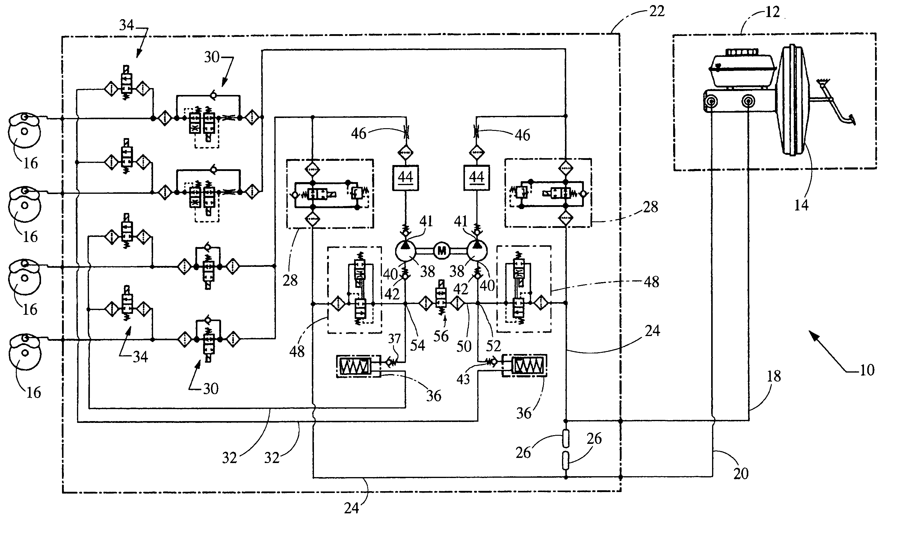
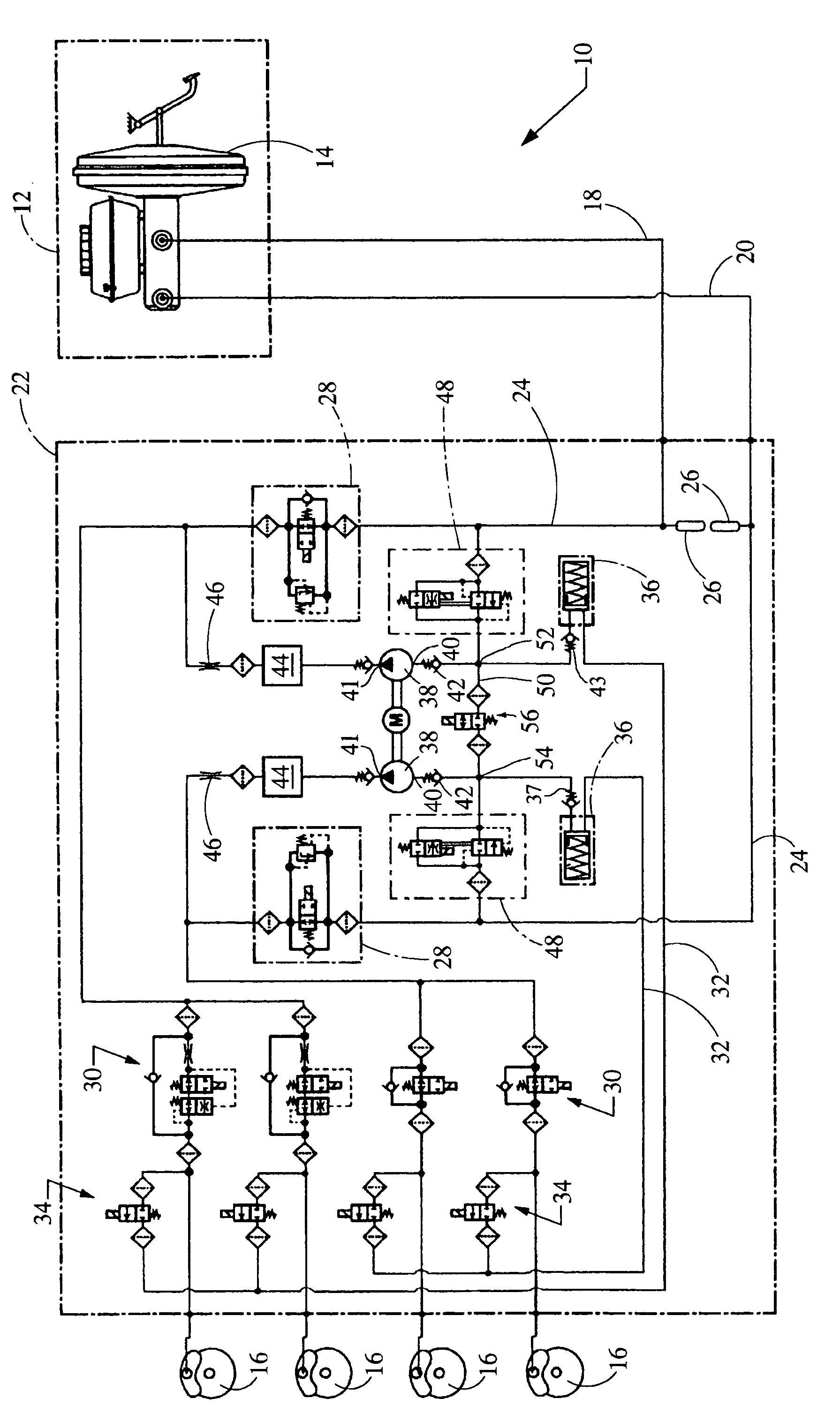
[0016]Referring to the Drawing, an exemplary dual-circuit hydraulic braking system 10 in accordance with the invention controls the flow of pressurized brake fluid from a brake actuation unit 12, such as a pedal-operated tandem master cylinder 14 that includes a vacuum brake booster by which to amplify the applied pedal force, to several wheel brakes 16 via a pair of braking circuits 18,20 conveniently housed within a hydraulic control unit 22. Each braking circuit 18,20 features a brake line 24 that receives pressurized fluid from the master cylinder 14 through a pulsation damper 26. Each brake line 24 includes a normally-open electrically-operated isolation valve 28 whose operation is controlled by a system controller (not shown). Each brake line 24 is also selectively connected to each of a pair of wheel brakes 16 through a dedicated normally-open electrically-operated inlet valve 30, also operated by the system controller, to achieve anti-lock vehicle braking, vehicle traction c...


PUM


Abstract

An automotive braking system controls the flow of pressurized brake fluid from a tandem master cylinder to several wheel brakes via a pair of braking circuits. Each circuit features a pressure relief line having, in series, a normally-closed valve, low-pressure accumulator, check valve, pump, damping chamber, and throttling orifice. A bypass line including a normally-closed bypass valve that is operated to interconnect the pressure relief lines of the first and second braking circuits proximate to the suction side of the pump, preferably downstream of the wheel brake outlet valves between the low-pressure accumulator and the check valve, selectively feeds fluid from one braking circuit to the other braking circuit to thereby reduce system response time when, for example, one or more wheel brakes driven by the other braking circuit is actuated to enhance vehicle traction or stability.

Description

FIELD OF THE INVENTION[0001]The invention relates to dual-circuit hydraulic braking systems for a motor vehicle that are controlled to enhance vehicle traction or stability.BACKGROUND OF THE INVENTION[0002]Modern dual-circuit hydraulic braking systems for automotive applications typically include an operator-actuated brake actuation unit, such as a tandem master cylinder actuated by a booster-aided brake pedal, by which to supply a first pressurized fluid to each of a first pair of wheel brakes via a first or “primary” braking circuit, and a second pressurized fluid to each of a second pair of wheel brakes via a second or “secondary” braking circuit. The use of wholly redundant braking circuits for operating discrete pairs of wheel brakes ensures continued vehicle braking capability, notwithstanding a degradation of performance of the one of the braking circuits.[0003]In order to achieve an “anti-lock” braking system, each braking circuit often features a normally-open electrically-...

Claims


Application Information

Patent Timeline
Patent Type & Authority Patents(United States)
IPC IPC(8): B60T8/34
CPCB60T8/348B60T8/4872
Inventor NAKAYASU, YUJI
Owner CONTINENTIAL TEVES INC
Why Eureka
Try Eureka