
Two-stage injection molding apparatus and method using interior fluid pressure

a technology of injection molding and fluid pressure, which is applied in the direction of food shaping, hollow objects, domestic applications, etc., can solve the problems of unnecessarily waste additional material, prolong the required preparation time for manufacturing, and lose surplus material

Inactive Publication Date: 2007-03-22
LANG MEKRA NORTH AMERICA LLC
View PDF5 Cites 0 Cited by
  • Summary
  • Abstract
  • Description
  • Claims
  • Application Information

AI Technical Summary

Benefits of technology

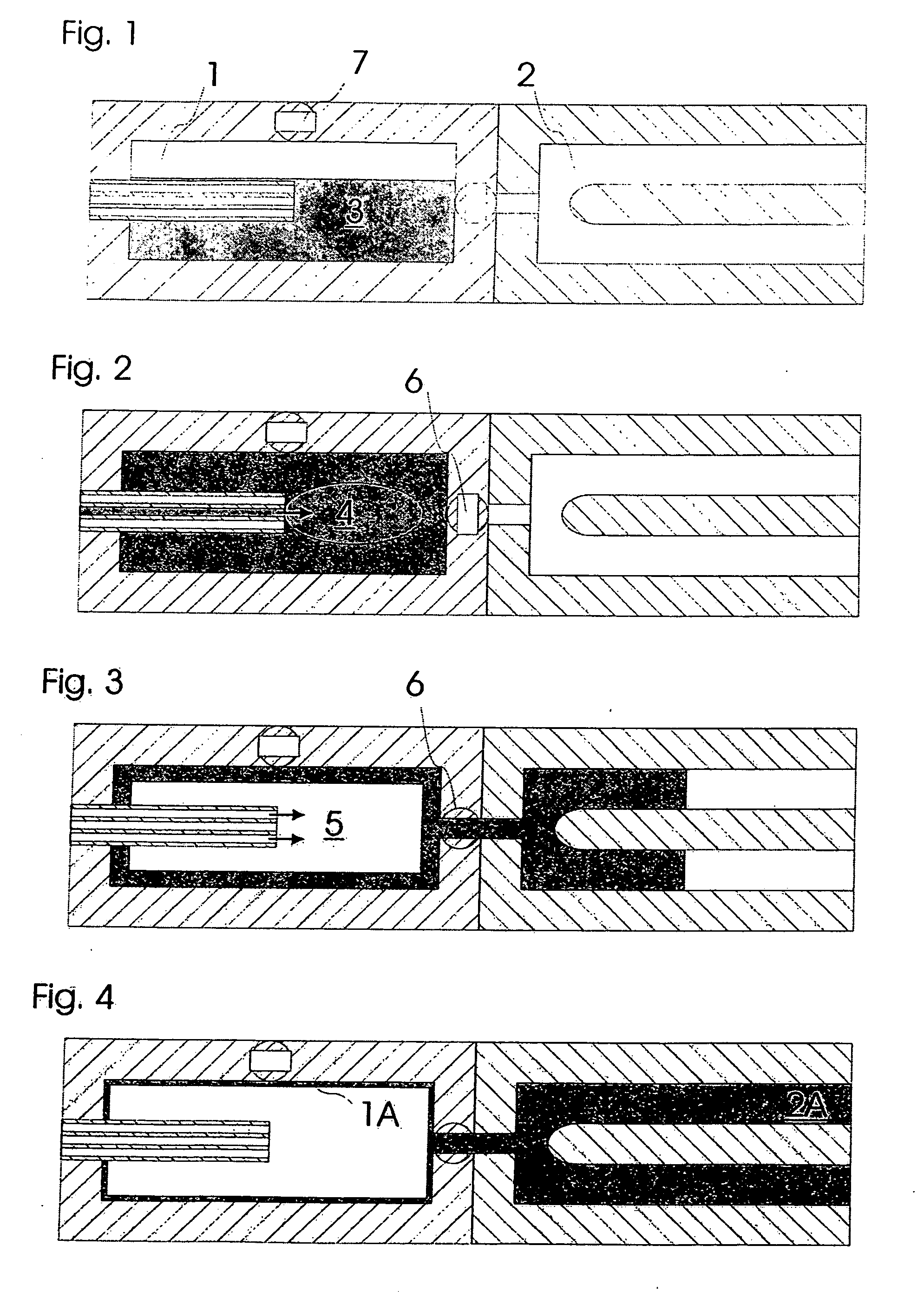
[0010] In this way, it becomes advantageously possible, that the previously lost material from a two stage liquid interior pressure method is brought into economical use and is available for the formation of a second master mold part and the said material need not be replasticized for this purpose. This is an energy saving step, since otherwise it would have been necessary to preheat the material again. All together, in this way, an available method is presented whereby the original two stage fluid interior pressure method can be employed in an efficient and economical manner.
[0013] The present invention encompasses, on this account, the possibility that the first mold cavity is initially a closed system during the filling of the plastic, workable material and / or during the subsequent introduction of the gas volume. This closure advantageously enables a rapid build-up of the desired hollow space, since the material has not yet altered itself away from its primary injected shape. The pressure of the gas volume can now hydraulically press the said plastic, workable material on an equal basis against the interior walls of the first mold. Then, only after the first mold is filled and / or the hollow space is built up within the first mold by means of the gas o volume, is a connection established to the second mold cavity. By means of the subsequently introduced liquid volume, again on the equalized basis, the hollow space of the first mold is enlarged and therewith the first master mold part is completely constructed, while the surplus, plastic workable material residing in the first mold is thereby ejected into the second mold to form a master mold part. In an especially fortunate manner, the first and the second molds communicate only during the introduction of the material, so that residual air present in the first mold can be expelled into the second mold and subsequently out of this second mold into the atmosphere. Subsequently, the closed connection is opened, so that the gas volume can quickly create a hollow space, without loss of pressure within the second mold.

Problems solved by technology

Such adjustments not only prolong the required preparation time for the manufacture, but also unnecessarily waste additional material.
The surplus material is lost, which has the effect of degrading the economy of the two-stage fluid interior pressure method.
Since, due to the thin wall thickness and the principally large hollow cavity, this loss of material occurs repeatedly in each manufacturing operation.
However, in the two stage method taught by DE 199 29700 A1, these residual materials are already reduced in temperature, because of the inevitable cooling caused by the injected liquid volume.
The result is that undesirable phase changes cause shrinkage and / or embedded solids in the operation of replasticization and recycling, Consequently, attempts at replasticization or using multiple replasticized material lead to inhomogeneities marring the resulting production.

Method used


Image

  • Two-stage injection molding apparatus and method using interior fluid pressure
  • Two-stage injection molding apparatus and method using interior fluid pressure

Examples


Embodiment Construction

[0025] Referring now in more detail to the drawings, the invention will now be described in more detail.

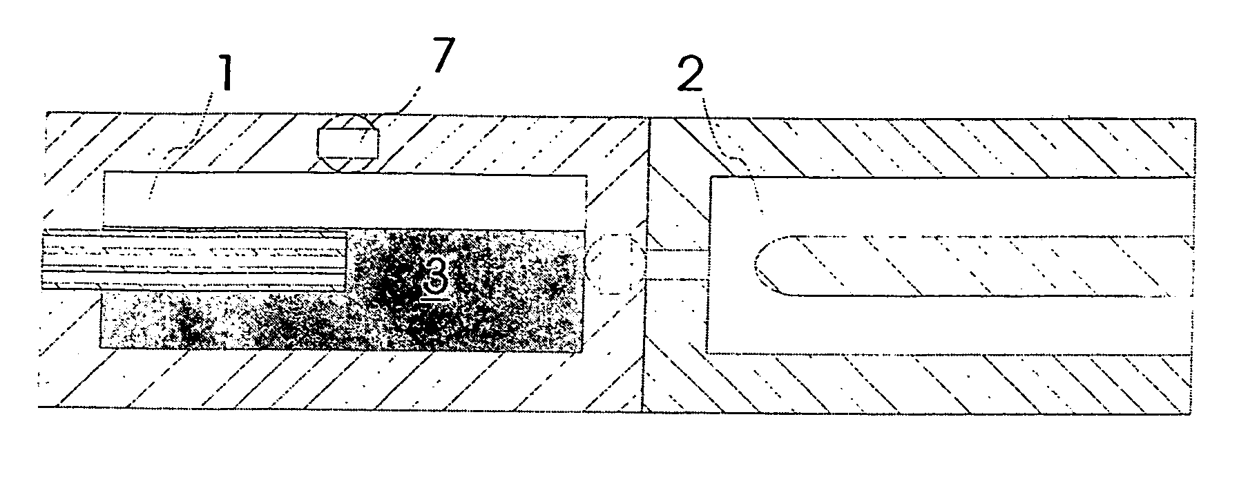
[0026] Figure shows schematically an apparatus for the carrying out of the invented method. This apparatus encompasses an injection mold A having a first mold cavity 1 and a second mold cavity 2. In the embodiment described above it is possible that both mold cavities can be separated from one another by a closed connection 6. In another embodiment (not shown) which, in the following explanation, corresponds to the described design, both molds 1, 2 are continually in communication with one another. In this case, one can also consider that connection 6 is always open.

[0027] It may be seen, that into the first mold 1, a plasticized, workable material 3 had formerly been introduced into the embodiment example through a feed valve 7. The valve was subsequently closed and remains closed during the ensuing method. This material introduction partially fills the first mold cavity 1. A c...


PUM

PropertyMeasurementUnit
Pressureaaaaaaaaaa
Volumeaaaaaaaaaa
Heataaaaaaaaaa

Abstract

The present invention concerns a two stage, injection molding apparatus and method for the manufacture of molded parts having operational steps of filling of a plasticized, workable material into a first mold introducing a volume of compressed gas and / or a liquid under pressure into the said workable material in order to expand this workable material and increase its volume to create a first molded part, and forcing surplus material out of the first mold into a second mold in order to form in a second molded part in the second cavity.

Description

BACKGROUND OF THE INVENTION [0001] The present invention is directed to a two stage, interior fluid pressure molding apparatus and method for the manufacture of master mold parts, especially for the fabrication of motor vehicle rear view mirrors or parts thereof. [0002] For the manufacturing of master mold parts with exceptionally thin walls, such as are exemplified by housings, carriers, or linkages of motor vehicle mirrors, interior fluid pressure methods are known. In regard to these known methods, initially a plastic, workable material, for example, a heated thermoplastic, is encapsulated within a closed hollow cavity of a casting mold. Subsequently, a volume of fluid under pressure is introduced into this cavity which hydraulically bears against the workable material causing the same to bond against the cavity walls. This forms an interior cavity within the reshaped material. Following the solidification of the molded material, a thin-walled master part can be removed. [0003] F...

Claims


Application Information

Patent Timeline
IPC IPC(8): B29C33/40
CPCB29C45/1706B29C2045/1709B29C2045/1707B29C45/1711
Inventor LANG, WERNERMEIER, MARKUS
Owner LANG MEKRA NORTH AMERICA LLC
Learn More